The Multibody Systems Approach to Vehicle Dynamics
Michael Blundell,Damian Harty
This is a test
This is a test
Buch teilen
768 Seiten
English
ePUB (handyfreundlich)
Über iOS und Android verfügbar
eBook - ePub
The Multibody Systems Approach to Vehicle Dynamics
Michael Blundell,Damian Harty
Angaben zum Buch
Buchvorschau
Inhaltsverzeichnis
Quellenangaben
Über dieses Buch
Filling the gaps between subjective vehicle assessment, classical vehicle dynamics and computer-based multibody approaches, The Multibody Systems Approach to Vehicle Dynamics offers unique coverage of both the virtual and practical aspects of vehicle dynamics from concept design to system analysis and handling development.
The book provides valuable foundation knowledge of vehicle dynamics as well as drawing on laboratory studies, test-track work, and finished vehicle applications to gel theory with practical examples and observations. Combined with insights into the capabilities and limitations of multibody simulation, this comprehensive mix provides the background understanding, practical reality and simulation know-how needed to make and interpret useful models.
New to this edition you will find coverage of the latest tire models, changes to the modeling of light commercial vehicles, developments in active safety systems, torque vectoring, and examples in AView, as well as updates to theory, simulation, and modeling techniques throughout.
Unique gelling of foundational theory, research findings, practical insights, and multibody systems modeling know-how, reflecting the mixed academic and industrial experience of this expert author team
Coverage of the latest models, safety developments, simulation methods, and features bring the new edition up to date with advances in this critical and evolving field
Häufig gestellte Fragen
Wie kann ich mein Abo kündigen?
Gehe einfach zum Kontobereich in den Einstellungen und klicke auf „Abo kündigen“ – ganz einfach. Nachdem du gekündigt hast, bleibt deine Mitgliedschaft für den verbleibenden Abozeitraum, den du bereits bezahlt hast, aktiv. Mehr Informationen hier.
(Wie) Kann ich Bücher herunterladen?
Derzeit stehen all unsere auf Mobilgeräte reagierenden ePub-Bücher zum Download über die App zur Verfügung. Die meisten unserer PDFs stehen ebenfalls zum Download bereit; wir arbeiten daran, auch die übrigen PDFs zum Download anzubieten, bei denen dies aktuell noch nicht möglich ist. Weitere Informationen hier.
Welcher Unterschied besteht bei den Preisen zwischen den Aboplänen?
Mit beiden Aboplänen erhältst du vollen Zugang zur Bibliothek und allen Funktionen von Perlego. Die einzigen Unterschiede bestehen im Preis und dem Abozeitraum: Mit dem Jahresabo sparst du auf 12 Monate gerechnet im Vergleich zum Monatsabo rund 30 %.
Was ist Perlego?
Wir sind ein Online-Abodienst für Lehrbücher, bei dem du für weniger als den Preis eines einzelnen Buches pro Monat Zugang zu einer ganzen Online-Bibliothek erhältst. Mit über 1 Million Büchern zu über 1.000 verschiedenen Themen haben wir bestimmt alles, was du brauchst! Weitere Informationen hier.
Unterstützt Perlego Text-zu-Sprache?
Achte auf das Symbol zum Vorlesen in deinem nächsten Buch, um zu sehen, ob du es dir auch anhören kannst. Bei diesem Tool wird dir Text laut vorgelesen, wobei der Text beim Vorlesen auch grafisch hervorgehoben wird. Du kannst das Vorlesen jederzeit anhalten, beschleunigen und verlangsamen. Weitere Informationen hier.
Ist The Multibody Systems Approach to Vehicle Dynamics als Online-PDF/ePub verfügbar?
Ja, du hast Zugang zu The Multibody Systems Approach to Vehicle Dynamics von Michael Blundell,Damian Harty im PDF- und/oder ePub-Format sowie zu anderen beliebten Büchern aus Technik & Maschinenbau & Automobil- & Transportbranche. Aus unserem Katalog stehen dir über 1 Million Bücher zur Verfügung.
This chapter is intended to document the emergence of multibody systems and provide an overview of their role in vehicle design and development. Previous work by contributors including Olley, Segel, Milliken, Crolla and Sharp is identified providing a historical perspective on the subject during the latter part of the twentieth century. Vehicle Dynamics as an engineering discipline is discussed together with the needs for analysis. Classical methods, analytical processes and computational methods are described together with computer packages.
To undertake a numerical process without knowledge of the difference between good and bad numbers is folly.
Damian Harty, 2014
1.1. Overview
In 1969, man travelled to the moon and back, using mathematics invented by Kepler, Newton and Einstein to calculate trajectories hundreds of thousands of miles long and spacecraft with less on-board computing power than a mobile telephone.1 With today's computing power and the mathematical frameworks handed down to us by Newton and Lagrange, it is scarcely credible that the motor car, itself over 100years old, can exercise so many minds and still show scope for improvement. Yet we are still repeating errors in the dynamic design of our vehicles that were made in the 1960s. Every car will spin – rotate excessively about a vertical axis until it is no longer pointing where it is going – if driven through an emergency lane change at highway speed without skilled correction from the driver or from computer-controlled stability systems (or both).
Legislation now demands embedded electronic control of brake systems to retain control and stability of vehicles although the driver still retains executive control in terms of choosing speed and path. However, with the exception of braking performance, road vehicle manufacturers are not currently forced by legislation to achieve a measurable standard of vehicle handling and stability. International standards exist that outline procedures for proving ground tests with new vehicles but these are nothing more than recommendations. Vehicle manufacturers make use of many of the tests but in the main will develop and test vehicles using in-company experience and knowledge to define the test programme.
In the absence of legislated standards, vehicle manufacturers are driven by market forces. Journalists report favourably on vehicles they enjoy driving – whether or not these are safe in the hands of the general public – and the legal profession seeks every opportunity to blur the distinction between bad driving and poor vehicle design. Matters are further complicated by market pressures driving vehicle designs to be too tall for their width – city cars and sport-utility vehicles have this disadvantage in common.
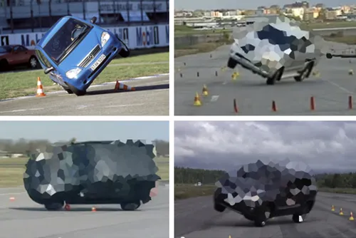
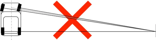
The growth in media attention and reporting to the public is undoubtedly significant. When the first edition was written, the most well-publicised example of this was the reported rollover of the Mercedes A Class (top left image in Figure 1.1) during testing by the Motoring Press. The test involves a slalom type manoeuvre and became popularly known as the ‘Elk Test’ or ‘Moose Test’. With the arrival of YouTube in 2005, everyone is a journalist. A short search netted three more examples of well-performed tests illustrating other vehicles in disarray. No manufacturer wants videos like these going viral.
It seems to the authors that there are two camps for addressing the vehicle dynamics problem. In the first camp are the practical ride and handling experts. Skilled at the driving task and able to project themselves into the minds of a variety of different possible purchasers of the vehicle, they are able to quickly take an established vehicle design and adjust its character to make it acceptable for the market into which it will be launched. Rarely, though, are experts from this camp called upon to work in advance on the concept or detail of the vehicle design.
The second camp contains theoretical vehicle dynamics experts. They are skilled academics in the mould of Leonard Segel who in 1956 published his ‘Theoretical prediction and experimental substantiation of the responses of the automobile to steering control’ (Segel, 1956).
FIGURE 1.1 Two-wheel lift abounds. (Top left – Mercedes courtesy of Auto Motor und Sport). There are two very similar tests being used, one is the ISO3888 Lane Change and the other is an ADAC avoidance test.
FIGURE 1.2 What vehicle dynamics looks like to outsiders.
Segel's work, and that of others from this era including the earlier work ‘Road manners of the modern motor car’ (Olley, 1945), laid the ground for all subsequent ‘classical’ vehicle dynamic analysis and forms a firm foundation upon which to build. It is rare for an expert from this camp to be part of the downstream vehicle development process.
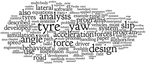
These two camps, a little like England and the USA, are ‘separated by a common language’.2 They use similar terms very differently (Figure 1.2) and can often have contemptuous relationships in a given organisation.
The ‘word cloud’ diagram in Figure 1.2 was generated by taking the contents of this chapter and pasting them into www.wordle.net. After removing some trivial common words, this is what remains. The size of the word reflects how often it appears; it seems that conversations about vehicle dynamics are dominated by talk of tyres and yaw. The latter is a rotation of the vehicle about a vertical axis.
1.2. What is vehicle dynamics?
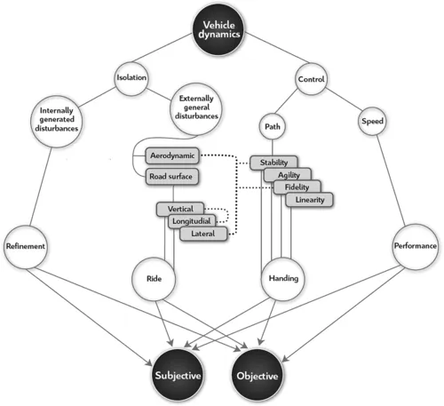
The field known as vehicle dynamics is concerned with two aspects of the behaviour of the machine. The first is isolation and the second is control. Figure 1.3 is the authors' subjective illustration of the intricacy and interconnection of the tasks to be approached; it is not claimed to be authoritative or complete but is rather intended as a thought-starter for the interested reader.
Isolation is about separating the driver from disturbances occurring as a result of the vehicle operation. This, too, breaks into two topics; disturbances the vehicle generates itself (engine vibration and noise, for example) and those imposed upon it by the outside world. The former category is captured by the umbrella term ‘refinement’. The disturbances in the latter category are primarily road undulations and aerodynamic interaction of the vehicle with its surroundings – crosswinds, wakes of structures and wakes of other vehicles. The behaviour of the vehicle in response to road undulations is referred to as ‘ride’ and could conceivably be grouped with refinement, though it rarely is in practice.
FIGURE 1.3 Vehicle dynamics interactions.
There is some substantial crossover in aerodynamic behaviour between isolation and control, since control implies the rejection of disturbances (‘fidelity’) and an absence of their amplification (‘stability’). Similarly, one response to road disturbances is a change in the vertical load supported by the tyre; this has a strong influence on the lateral force the tyre is generating at any given instant in time and is thus crucial for both fidelity and stability. It can be seen with some little reflection that one of the difficulties of vehicle dynamics work is not the complexity of the individual effects being considered but rather the complexity of their interactions.
Control is concerned largely with the behaviour of the vehicle in response to driver demands. The driver continuously varies both path curvature and speed, subject to the limits of the vehicle capabilities, in order to follow an arbitrary course.
FIGURE 1.4 Geometric approximations of vehicle behaviour are incorrect.
Speed variation is governed by vehicle mass and tractive power availability at all but the lowest speed, and is easily understood. Within the performance task, issues such as unintended driveline oscillations and tractive force variation with driver demand may interact strongly with the path of the vehicle.
The adjustment of path curvature at a given speed is altogether more interesting. In a passenger car, the driver has a steering wheel, which for clarity will be referred to as a handwheel3 throughout the book. The handwheel is a ‘yaw rate’ demand – a demand for rotational velocity of the vehicle when viewed from above. The combination of a yaw rate and a forward velocity vector that rotates with the vehicle gives rise to a curved path. There is a maximum path curvature available in normal driving, which is the turning circle, available only at the lowest speeds.
It is generically true that the vehicle does not behave in a ‘geometric’ manner and its radius of turn cannot usefully be predicted by considering the angle of the front wheels relative to the rear wheels, except below around 30mph.
The geometric view (Figure 1.4) becomes increasingly inaccurate as speed increases and can lead to an over-estimate of vehicle responses by a factor of up to four at European highway speeds. The lower-than-geometric response of the car is a consequence of pneumatic tyres and modern vehicle engineering practice; it is not necessarily the ‘unengineered’ behaviour of all vehicle layouts.
In normal circumstances (that is to say in day-to-day road use) the driver moves the handwheel slowly and is well within the limits of the vehicle capability. The vehicle has no difficulty responding to the demanded yaw rate. If the driver increases yaw rate demand slightly then the vehicle will increase its yaw rate by a proportional amount (Figure 1.5). This property is referred to as ‘linearity’; the vehicle is described as ‘linear’. For the driver, the behaviour of the vehicle is quite instinctive. A discussion of the analysis and interpretation of vehicle non-geometric behaviour, linearity and departure from linearity is given in Chapter 7.
In the linear region, the behaviour of the vehicle can be represented as a connected series of ‘steady state’ events. Steady state is the condition in which, if the handwheel remains stationary then all the vehicle states – speed, yaw rate, path curvature and so on – remain constant and is more fully defined in Chapter 7. The steady state condition is easy to represent using an equilibrium analogy, constructed with the help of so-called ‘centrifugal force’. It should be noted that this fictitious force is invented solely for convenience of calculation of the analogous equilibrium state or the calculation of forces in an accelerating frame of reference. When a vehicle is travelling on a curved path it is not in equilibrium.
FIGURE 1.5 Linearity: More handwheel input results in proportionally more yaw rate.
The curved path of the vehicle requires some lateral acceleration. Correctly, the lateral acceleration on a cornering vehicle is a centripetal acceleration – ‘centre seeking’. Note that speed is not the same as velocity; travelling in a curved path with a constant speed implies a changing direction and therefore a changing velocity. Even the centripetal acceleration definition causes some problems since everyone ‘knows’ that they are flung to the outside of a car if unrestrained and so there is much lax t...