Effective stroke therapy can be improved through real-time monitoring of the neurological and cardiovascular responses to treatment. This requires crucial knowledge on behalf of both the sonographer and stroke physician to make the best decisions for the patient so as to minimize the damage caused by the original stroke and the risk of further stroke.
Cerebrovascular Ultrasound in Stroke Prevention and Treatment, Second Edition, takes a practical approach to the examination of patients, the interpretation of ultrasound studies and the application of cerebrovascular ultrasound in the development of management and treatment studies, assisting neurologists, radiologists, and ultrasonographers in stroke therapy.
Trusted by 375,005 students
Access to over 1.5 million titles for a fair monthly price.
Andrei V. Alexandrov1, Alice Robinson-Vaughn1, Clotilde Balucani2 & Marsha M. Neumyer3
1University of Alabama Hospital, Birmingham, AL, USA
2University of Alabama Hospital, Birmingham, AL, USA and University of Perugia, Perugia, Italy
3Vascular Diagnostic Educational Services, Harrisburg, PA, USA
Introduction
A simple observation gives origins to clinical examinations, analysis and scientific exploration. Being able to observe Nature at work or in distress often offers clues that clinicians and scientists need to get an idea as to what could be going on and come up with a hypothesis to explain it. Ultrasound, with its unprecedented temporal resolution, is an elegant tool to probe living tissues. This first chapter describes how we evaluate the extracranial vasculature, then subsequent chapters continue the journey into cerebral vessels, hemodynamics and specific disease states.
Anatomy of the cerebrovascular arterial system
The choice of transducer placement and subsequent repositioning determines the success of visualizing the target structures and staying with the spatial course of the pre-cerebral vessels. Therefore, sonographers performing vascular ultrasound examinations must think “in 3-D,” or three dimensions, about the vessel being investigated and put together transducer positioning with vessel intercept and further “go with the structure or flow” to complete scanning.
A sonographer should further imagine how this arterial segment would look on an angiogram. We strongly encourage those learning and interpreting ultrasound to be familiar with cerebral angiograms [1] since angiography is the gold standard for the assessment of the accuracy of ultrasound testing, and ultrasound performance is often judged by vessel appearance on invasive or non-invasive angiograms. The following section deals with normal vascular anatomy and describes a standard protocol for carotid and vertebral duplex testing on the neck. More details of anatomy and angiographic images are provided in Chapter 3.
The common carotid artery
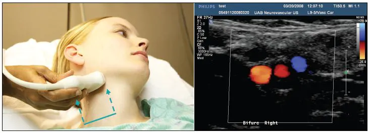
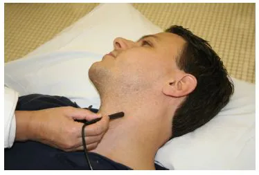
Scanning starts with a quick brightness-modulated (B-mode) surveillance in a transverse transducer position of the common carotid artery (CCA) up to its bifurcation. Color flow or power mode can be added to visualize flow in the vessel lumen (Figure 1.1).
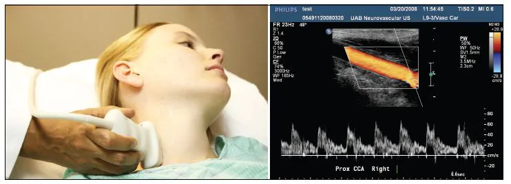
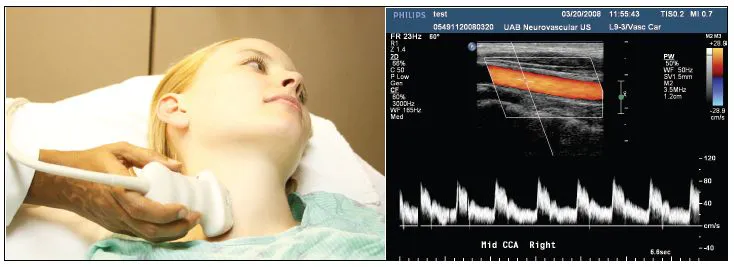
On the right, the brachiocephalic trunk or innominate artery, arises from the aortic arch and then bifurcates into the subclavian artery and the CCA. On the left side, both the common carotid artery and the left subclavian artery usually originate directly from the aortic arch. The CCA is easily assessable on the neck where it runs in parallel with the jugular vein and the initial assessment starts right above the clavicle (Figure 1.2). It is further assessed in its mid-portion as the transducer slides cephalad over the sternocleido-mastoid muscle (Figure 1.3).
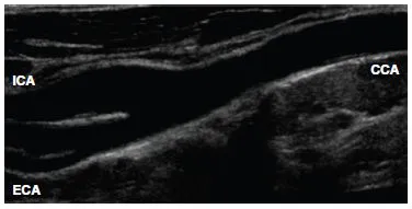
At approximately the level of the fourth vertebra, which is at the level of the upper border of the thyroid cartilage, the CCA bifurcates into the internal and external carotid arteries (Figure 1.4). The carotid bulb represents dilatation at the distal CCA extending into the proximal internal carotid artery. The carotid bulb bears unique flow patterns yielding a boundary separation zone and its wall has numerous baroand chemo-receptors. The size and location of the carotid bulb are variable.
Most atherosclerotic disease occurs at the level of the bifurcation due to marked changes in vessel geometry resulting in increased shear stress, fluid stagnation and increased particle residence time on the postero-lateral wall of the bulb [2].
The internal carotid artery
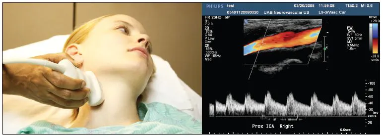
Beyond the carotid bulb, the internal carotid artery (ICA) returns to a normal caliber (Figure 1.5) and courses in a relatively straight line up the neck into the skull to supply blood flow to the eye and brain. As a rule, the ICA has no branches within the neck. After entering the skull, the ICA makes an S-shaped curve in the region of the carotid siphon. The ICA entrance to the skull marks a vulnerable area where arterial wall dissections may occur due to fixed ICA position. The first major branch of the ICA is the ophthalmic artery that supplies the eye. After giving off the ophthalmic artery, the ICA divides into the middle cerebral artery (MCA) and the anterior cerebral artery (ACA), a part of the circle of Willis. This is covered in Chapters 2 and 3.
Figure 1.1 Transverse positioning of the duplex transducer depicts carotid bifurcation on the neck. Arrows indicate a proximal initial placement of the probe and its ascent to the bifurcation as the initial step to extracranial vascular examination. The left side of the ultrasound B-mode and color flow image is oriented towards the midline. Red color shows arterial flows, blue indicates the jugular vein.
Figure 1.2 After transverse sweeps, a longitudinal position of the probe yields depiction of the proximal common carotid artery close to its origin from the brachio-cephalic trunk on the right side of the neck. Note that ultrasound image is aligned with the middle of the vessel by keeping “the ends of pipe open.” The left side of the ultrasound image is oriented cephalad. Doppler sampling shows the velocity spectra at a 60
angle of insonation.
Figure 1.3 A longitudinal view of the mid-cervical portion of the right carotid artery shows B-mode, color flow and Doppler spectra of the artery and flow through it.
Figure 1.4 The “tuning fork” of the carotid bifurcation on B-mode.
The external carotid artery
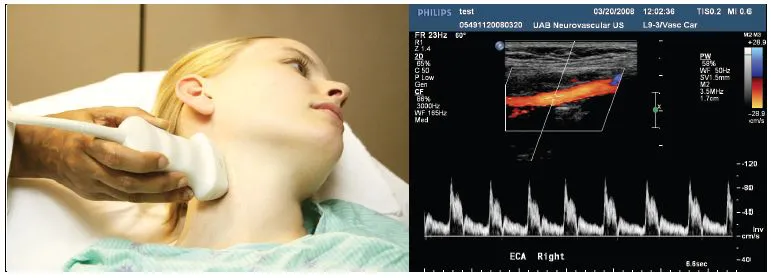
The extracranial carotid artery (ECA) supplies the muscles of the face, forehead and scalp (Figure 1.6). To switch between the ICA and ECA, a sonographer often must reposition the transducer from lateral to more medial angulation since both vessels are seldom visualized together in one plane for sufficient interrogation. The ECA has branches that could be visible while scanning its proximal segment. The ICA divides into eight branches on the neck. Several of these branches, i.e. ascending pharyngeal, facial, internal maxillary and superficial temporal arteries, communicate via anastomoses with the ICA. The occipital artery is the only ECA branch that communicates with the vertebral artery circulation. It is important to recognize these branches because the ECA fairly often becomes a collateral source for blood flow to the brain when the ICA is critically stenosed or occluded.
The vertebral artery
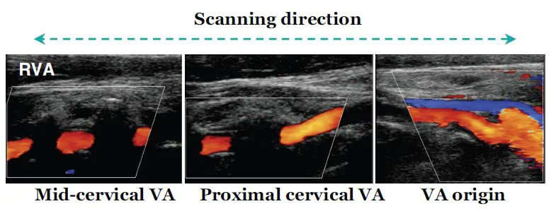
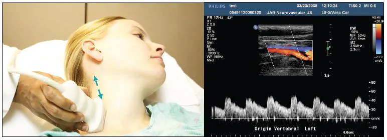
The vertebral arteries (VA) arise from the subclavian arteries and its origin can be found with transducer sliding towards the clavicle and aiming deep and lateral to the CCA (Figure 1.7). The VA passes medially in the neck to enter the bony canal at the C6 vertebrae and it further courses cephalad through the transverse processes of the vertebrae (Figure 1.8). It enters the base of the skull by looping around the atlas and ascending through the foramen magnum. At this point, the right and left vertebral arteries join together to form the basilar artery. The basilar artery terminates in the posterior cerebral arteries, which make up the posterior portion of the circle of Willis.
Components of ultrasound examination
Continuous wave (CW) Doppler
Although this technology is now regarded more of historic interest due to technological advances in imaging, knowledge of CW Doppler is required for board examinations and occasionally the skill of using the so-called “pencil probe” may be useful.
Dr Eugene Strandness and co-workers first reported the use of a transcutaneous flowmeter to evaluate occlusive arterial disease in 1966 [3]. Extracranial carotid and vertebral examinations with CW Doppler were reported by Drs Merrill Spencer and Michael von Reutern and colleagues in the 1970s [4,5].
Figure 1.5 Insonation of the proximal ICA just after the bulb.
Figure 1.6 Insonation of the ECA: color flow image shows a branch while Doppler spectra display a characteristic high resistance waveform.
Figure 1.7 Insonation of the origin of the vertebral artery. Arrows show the further extent of the vertebral artery examination on the neck.
Figure 1.8 Doppler spectra in a proximal cervical segment of the vertebral artery visualized with B-mode and color flow.
Figure 1.9 Insonation with continuous wave (CW) transducer.
With this technology, one crystal continuously emits the signal and another crystal continuously receives returned echoes, and this “non-imaging” transducer looks like a pencil (Figure 1.9). CW Doppler displays Doppler frequency shifts including maximum frequency trace without an artifact due there being no limitations related to pulse repetition frequency. Current CW systems can differentiate between positive and negative Doppler shifts and create a bi-directional spectral signal that shows flow direction as towards or away from the transducer. However, CW Doppler shows no information regarding the structure, i.e. image, or the depth from which the signals originated.
The advantage of this ultrasound test is its ability to display Doppler frequency shifts from moving objects without an artifact called aliasing. With the recent development of direct imaging and pulsed wave Doppler methods, CW Doppler is rarely performed and is not reimbursed in the United States as a sole test used for evaluation of the carotid vessels. Perhaps the only remaining indications for CW Doppler for carotid arteries are extensive (>2 cm) shadowing of the bifurcation, arterial lesions extending above the level of lower jaw or a quick bifurcation screening before or with (not as a substitute for) direct imaging investigation.
The B-mode image
The B-mode image is created from the amplitude of backscattered echo signals that are displayed in gray scale along beam propagation (depth) and the length of transducer/skin interface (Figures 1.1 and 1.2). The gray shade of the signal on-screen displays the strength of the returning echo while its location relates to the depth of tissue reflector. Several crystals are sequentially activated with electronic pulses or the transducer is rotated mechanically (steering) to create multiple scan lines. The scan lines are put together to generate an image (or “frame”). Since the average speed of sound propagation in soft tissues is 1540 m s–1 (“a mile per second”), multiple frames are generated in a second, creating an illusion of a real-time picture (“movie making” with ultrasound).
The maximum depth of sound penetration is determined by the emitting frequency of the ultrasound transducer, which is usually 4–12 MHz for extracranial imaging and 2–4 MHz for intracranial imaging. Higher frequencies have smaller pulse lengths and allow better spatial resolution but less penetration due to increased sound scattering. Timegain compensation (TGC) is applied to improve visualization of structures with increasing depths of insonation. The smallest distinguishable distance between two reflectors along the ultrasound beam axis (axial resolution) is directly proportional to the spatial length of the pulse. Lateral resolution (or resolution perpendicular to the direction of an ultrasound beam) is also dependent on transducer geometry since it is the highest in the focal zone. The focal zone is determined as the narrowest point between converging (nearfield) and diverging (far-field) parts of the ultrasound beam. Note that an ultrasound scanner can create multiple focal zones to optimize different parts of the image. Therefore, linear or curved array transducers with larger surface, dynamic electronic focusing and multiple narrow width beams have better lateral resolution.
B-mode imaging artifacts include the following:
1 Shadowing (no image can be generated along ultrasound beam axis behind a bright reflector). Changing the transducer position and planes of insonation may minimize shadow appearance. Shadows can originate from perpendicular insonation of vessel walls, plaque calcification (Figure 1.7) and transverse vertebral processes (Figure 1.3).
2 Reverberation (multiple bright echoes that often have a regular shape and layered position are displayed along the axis of ultrasound beam when echoes bounce many times between two strong reflectors).
3 Mirror image [a false image (also known as phantom image or reflection artifact) is created when obliquely scanning a strongly reflecting boundary]. Vessel visualization in transverse and longitudinal planes often resolves confusion associated with this artifact.
4 Plane-of-section (three-dimensional structure is inadequately displayed on a two-dimensional monitor). Using imagination for three-dimensional spatial relationships, the transducer position should be changed to generate adequate sectional planes.
B-mode imaging is used to identify the carotid and vertebral arteries, carotid intima–media complex, atherosclerotic plaques and anatomic anomalies. B-mode imaging can also be used to perform intracranial studies where it shows contralateral skull line, midline structures including the third ventricle and brain parenchymal structures.
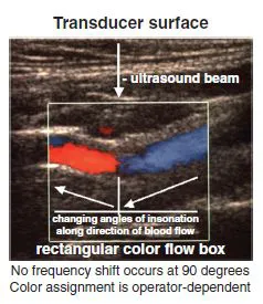
Figure 1.10 Changes in color flow assignment relative to the middle of the transducer within a rectangular color flow box.
The color-flow Doppler image
Color-coded Doppler flow image (CDFI) displays the average (or mean) shifts in the frequency of returned echoes backscattered from moving objects, usually red blood cells. The color scale can be selected manually, ranging from two colors (red and blue) to a rainbow palette. At least two distinctly different colors are used to display clearly the direction of flow relative to transducer midline (Figure 1.10). According to the Doppler effect, objects moving towards the transducer will increase the frequency of backscattered echoes relative to emitted frequency and vice versa. However, color assignments are operator dependent.
Therefore, CDFI is used to identify moving blood and display the direction of flow. No Doppler frequency shift occurs at a 90° angle between ultrasound bea...
Table of contents
Cover
Title
Copyright
List of Contributors
Preface
Foreword
Preface to the First Edition
Foreword to the First Edition
Acknowledgment
Practice of Ultrasound: an Introduction
Part I How to Perform Ultrasound Tests
Part II Hemodynamic Principles
Part III Criteria for Interpretation
Part IV Ultrasound in Stroke Prevention and Treatment
Index
Frequently asked questions
Yes, you can cancel anytime from the Subscription tab in your account settings on the Perlego website. Your subscription will stay active until the end of your current billing period. Learn how to cancel your subscription
No, books cannot be downloaded as external files, such as PDFs, for use outside of Perlego. However, you can download books within the Perlego app for offline reading on mobile or tablet. Learn how to download books offline
Perlego offers two plans: Essential and Complete
Essential is ideal for learners and professionals who enjoy exploring a wide range of subjects. Access the Essential Library with 800,000+ trusted titles and best-sellers across business, personal growth, and the humanities. Includes unlimited reading time and Standard Read Aloud voice.
Complete: Perfect for advanced learners and researchers needing full, unrestricted access. Unlock 1.5M+ books across hundreds of subjects, including academic and specialized titles. The Complete Plan also includes advanced features like Premium Read Aloud and Research Assistant.
Both plans are available with monthly, semester, or annual billing cycles.
We are an online textbook subscription service, where you can get access to an entire online library for less than the price of a single book per month. With over 1.5 million books across 990+ topics, we’ve got you covered! Learn about our mission
Look out for the read-aloud symbol on your next book to see if you can listen to it. The read-aloud tool reads text aloud for you, highlighting the text as it is being read. You can pause it, speed it up and slow it down. Learn more about Read Aloud
Yes! You can use the Perlego app on both iOS and Android devices to read anytime, anywhere — even offline. Perfect for commutes or when you’re on the go. Please note we cannot support devices running on iOS 13 and Android 7 or earlier. Learn more about using the app
Yes, you can access Cerebrovascular Ultrasound in Stroke Prevention and Treatment by Andrei V. Alexandrov in PDF and/or ePUB format, as well as other popular books in Medicine & Medical Technology & Supplies. We have over 1.5 million books available in our catalogue for you to explore.