![]()
PREFACE.
THE want of a comprehensive collection of illustrations and descriptions of MECHANICAL MOVEMENTS has long been seriously felt by artisans, inventors, and students of the mechanic arts. It was the knowledge of this want which induced the compilation of the collection here presented. The movements which it contains have been already illustrated and described in occasional installments scattered through five volumes of the AMERICAN ARTISAN, by the readers of which their publication was received with so much favor as was believed to warrant the expense of their reproduction with some revision in a separate volume.
The selection of the movements embraced in this collection has been made from many and various sources. The English works of Johnson, Willcock, Wylson, and Denison have been drawn upon to a considerable extent, and many other works—American and foreign—have been laid under contribution ; but more than one-fourth of the movements—many of purely American origin—have never previously appeared in any published collection. Although the collection embraces about three times as many movements as have ever been contained in any previous American publication, and a considerably larger number than has ever been contained in any foreign one, it has not been the object of the compiler to merely swell the number, but he has endeavored to select only such as may be of really practical value ; and with this end in view, he has rejected many which are found in nearly all the previously published collections, but which he has considered only applicable to some exceptional want.
Owing to the selection of these movements at such intervals as could be snatched from professional duties, which admitted of no postponement, and to the engravings having been made from time to time for immediate publication, the classification of the movements is not as perfect as the compiler could have desired; yet it is believed that this deficiency is more than compensated for by the copiousness of the Index and the entirely novel arrangement of the illustrations and the descriptive letter-press on opposite pages, which make the collection—large and comprehensive as it is—more convenient for reference than any previous one.
![]()
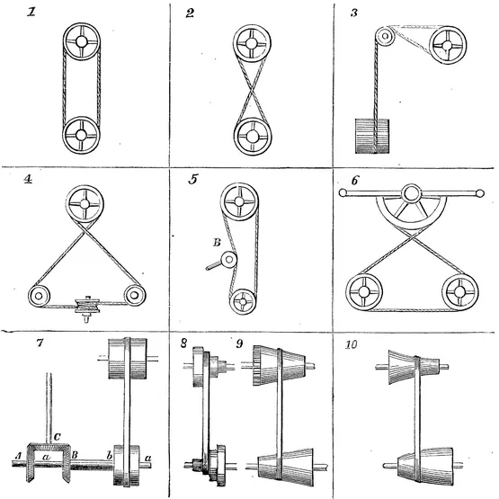
1. Illustrates the transmission of power by simple pulleys and an open belt. In this case both of the pulleys rotate in the same direction.
2. Differs from 1 in the substitution of a crossed belt for the open one. In this case the direction of rotation of the pulleys is reversed.
By arranging three pulleys, side by side, upon the shaft to be driven, the middle one fast and the other two loose upon it, and using both an open and a crossed belt, the direction of the said shaft is enabled to be reversed without stopping or reversing the driver. One belt will always run on the fast pulley, and the other on one of the loose pulleys. The shaft will be driven in one direction or the other, according as the open or crossed belt is on the fast pulley.
3. A method of transmitting motion from a shaft at right angles to another, by means of guide-pulleys. There are two of these pulleys, side by side, one for each leaf of the belt.
4. A method of transmitting motion from a shaft at right angles to another whose axis is in the same plane. This is shown with a crossed belt. An open belt may be used, but the crossed one is preferable, as it gives more surface of contact.
5. Resembles 1, with the addition of a movable tightening pulley, B. When this pulley is pressed against the band to take up the slack, the belt transmits motion from one of the larger pulleys to the other ; but when it is not, the belt is so slack as not to transmit motion.
6. By giving a vibratory motion to the lever secured to the semi-circular segment, the belt attached to the said segment imparts a reciprocating rotary motion to the two pulleys below.
7. A method of engaging, disengaging, and reversing the upright shaft at the left. The belt is shown on the middle one of the three pulleys on the lower shafts, a, b, which pulley is loose, and consequently no movement is communicated to the said shafts. When the belt is traversed on the left-hand pulley, which is fast on the hollow shaft, b, carrying the bevel-gear, B, motion is communicated in one direction to the upright shaft; and on its being traversed on to the right-hand pulley, motion is transmitted through the gear, A, fast on the shaft, a, which runs inside of b, and the direction of the upright shaft is reversed.
8. Speed-pulleys used for lathes and other mechanical tools, for varying the speed according to the work operated upon.
9. Cone-pulleys for the same purpose as 8. This motion is used in cotton machinery, and in all machines which are required to run with a gradually increased or diminished speed.
10. Is a modification of 9, the pulleys being of different shape.
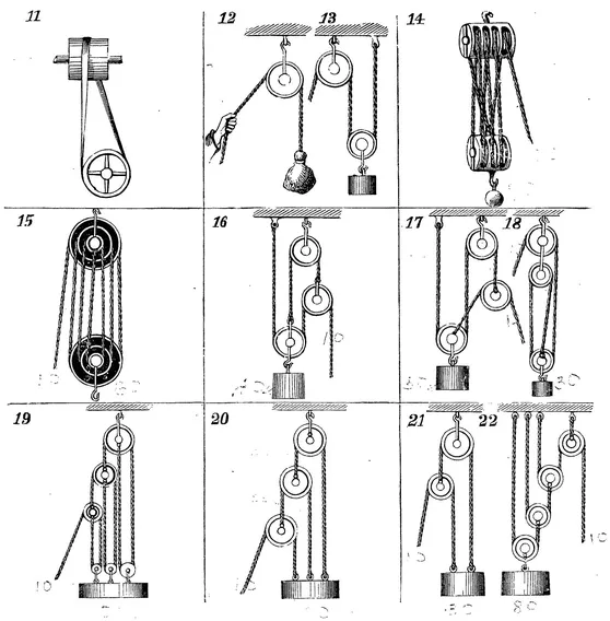
11. Another method of effecting the same result as 3, without guide-pulleys.
12. Simple pulley used for lifting weights. In this the power must be equal to the weight to obtain equilibrium.
13. In this the lower pulley is movable. One end of the rope being fixed, the other must move twice as fast as the weight, and a corresponding gain of power is consequently effected.
14. Blocks and tackle. The power obtained by this contrivance is calculated as follows: Divide the weight by double the number of pulleys in the lower block; the quotient is the power required to balance the weight.
15. Represents what are known as White’s pulleys, which can either be made with separate loose pulleys, or a series of grooves can be cut in a solid block, the diameters being made in proportion to the speed of the rope; that is, 1, 3, and 5 for one block, and 2, 4, and 6 for the other. Power as 1 to 7.
16 and 17. Are what are known as Spanish bartons.
18. Is a combination of two fixed pulleys and one movable pulley.
19, 20, 21, and 22. Are different arrangements of pulleys. The following rule applies to these pulleys :—In a system of pulleys where each pulley is embraced by a cord attached at one end to a fixed point and at the other to the center of the movable pulley, the effect of the whole will be = the number 2, multiplied by itself as many times as there are movable pulleys in the system.
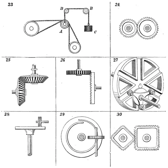
23. A contrivance for transmitting rotary motion to a movable pulley. The pulley at the bottom of the figure is the movable one; if this pulley were raised or depressed, the belt would be slackened or tightened accordingly. In order to keep a uniform tension on the belt, a pulley, A, carried in a frame sliding between guides (not shown), hangs from a rope. passing over the two guide-pulleys, B, B, and is acted upon by the balance weight, C, in such manner as to produce the desired result.
24. Spur-gears.
25. Bevel-gears. Those of equal diameters are termed “miter-gears.”
26. The wheel to the right is termed a “crown-wheel;” that gearing with it is a spur-gear. These wheels are not much used, and are only available for light work, as the teeth of the crown-wheel must necessarily be thin.
27. “Multiple gearing ”—a recent invention. The smaller triangular wheel drives the larger one by the movement of its attached friction-rollers in the radial grooves.
28. These are sometimes called “brush-wheels.” The relative speeds can be varied by changing the distance of the upper wheel from the center of the lower one. The one drives the other by the friction or adhesion, and this may be increased by facing the lower one with india-rubber.
29. Transmission of rotary motion from one shaft at right angles to another. The spiral thread of the disk-wheel drives the spur-gear, moving it the distance of one tooth at every revolution.
30. Rectangular gears. These produce a rotary motion of the driven gear at a varying speed. They were used on a printing-press, the type of which were placed on a rectangular roller.
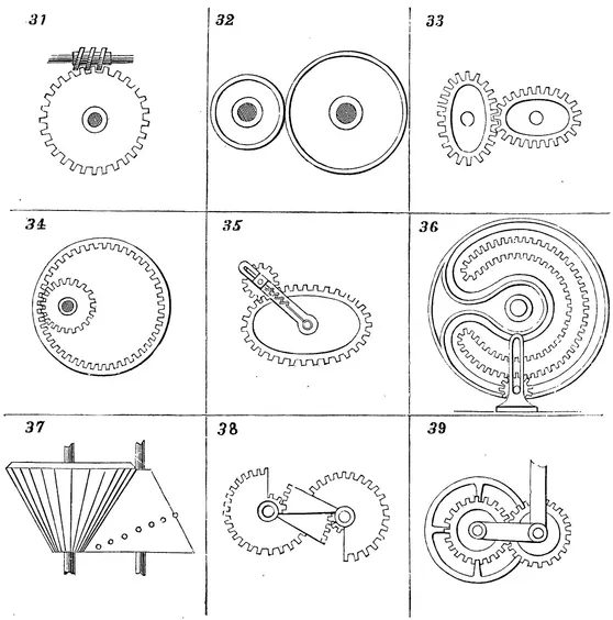
31. Worm or endless screw and a worm-wheel. This effects the same result as 29; and as it is more easily constructed, it is oftener used.
32. Friction-wheels. The surfaces of these wheels are made rough, so as to bite as much as possible; one is sometimes faced with leather, or, better, with vulcanized india-rubber.
33. Elliptical spur-gears. These are used where a rotary motion of varying speed is required, and the variation of speed is determined by the relation between the lengths of the major and minor axes of the ellipses.
34. An internally toothed spur-gear and pinion. With ordinary spur-gears (such as represented in 24) the direction of rotation is opposite; but with the internally toothed gear, the two rotate in the same direction; and with the same strength of tooth the gears are capable of transmitting greater force, because more teeth are engaged.
35. Variable rotary motion produced by uniform rotary motion. The small spur-pinion works in a slot cut in the bar, which turns loosely upon the shaft of the elliptical gear. The bearing of the pinion-shaft has applied to it a spring, which keeps it engaged; the slot in the bar is to allow for the variation of length of radius of the elliptical gear.
36. Mangle-wheel and pinion—so called from their application to mangles—converts continuous rotary motion of pinion into reciprocating rotary motion of wheel. The shaft of pinion has a vibratory motion, and works in a straight slot cut in the upright stationary bar to allow the pinion to rise and fall and work inside and outside of the gearing of the wheel. The slot cut in the face of the mangle-wheel and following its outline is to receive and guide the pinion-shaft and keep the pinion in gear.
37. Uniform into variable rotary motion. The bevel-wheel or pinion to the left has teeth cut through the whole width of its face. Its teeth work with a spirally arranged series of studs on a conical wheel.
38. A means of converting rotary motion, by which the speed is made uniform during a part, and varied during another part, of the revolution.
39. Sun-and-planet motion. The spur-gear to the right, called the planet-gear, is tied to the center of the other, or sun-gear, by an arm which preserves a constant distance between their centers. This was used as a substitute for the crank in a steam engine by James Watt, after the use of the crank had been patented by another party. Each revolution of the planet-gear, which is rigidly attached to the connecting-rod, gives two to the sun-gear, which is keyed to the fly-wheel shaft.
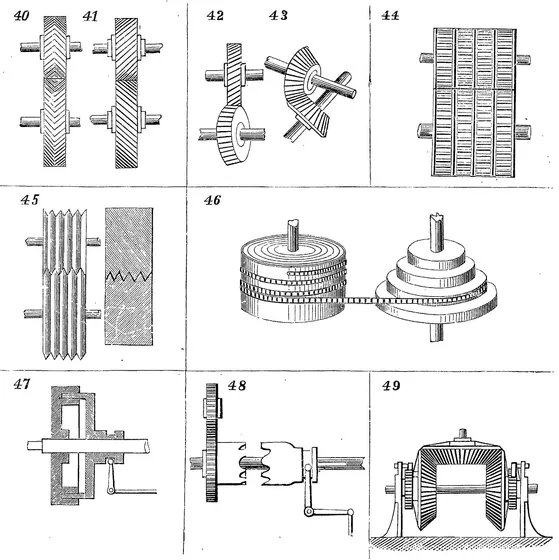
40 and 41. Rotary converted into rotary motion. The teeth of these gears, being oblique, give a more continuous bearing than ordinary spur-...