Most dam accidents with hydroelectric plants are due to under-dimensioning of the maximum floods of spillway design, causing extravasation and dam breaks (this occurs in 23% of the accidents). This work highlights the relationship between spillway design and potential dam failure and other important aspects of these structures and presents the methodology of design based on the international experience on the subject.
The book covers river basin studies and floods (the geology, geomorphology, hydrology, hydraulics, and layouts of the works). Further, spillway function, capacity and design flood, layouts, or arrangements, of hydroelectric works and types of spillways are treated in the book. Finally, the book discusses examples of dams that broke due to insufficient spillway capacity.
The book is intended for engineers and the companies that design dams and power plants around the world, as well as students in dam and hydraulic engineering. In short, people interested in producing electricity that is clean and potentially cheaper than other sources.
Trusted by 375,005 students
Access to over 1.5 million titles for a fair monthly price.
This book presents the methodology of design of spillways of hydroelectric power plants, step by step. It is understood that the basic concepts of hydraulics engineering and of rock erosion are well known to users. These principles are set out in basic texts cited in the references, as well as in articles and books available on the internet. However, where necessary, summaries of specific points will be presented.
The projects of the structures of the hydroelectric plants, including the spillways, have been carried out in accordance with the guidelines and criteria of the US Army Corps of Engineers and USBR publications: Hydraulic Design Criteria (1959); Design of Small Dams (1974); and USACE, Hydraulic Design of Spillways (1965). Mention should be made of ICOLD Bulletin No 58, Spillways for Dams (1987). In Brazil, these criteria can be found in Eletrobras/CBDB (2003), available on the internet.
1.1Initial considerations
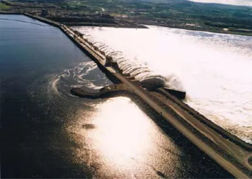
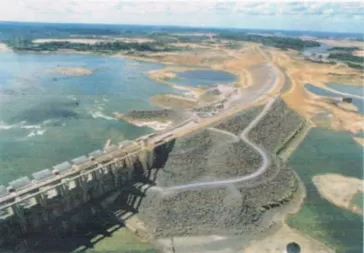
The following illustrations show the Tucuruí HPP in the Tocantins river, state of Pará, Brazil. Figure 1.1A shows part of the right dam, the spillway and powerhouse and the left abutment. Figure 1.1B shows part of the spillway, the right dam and the right abutment. The dam is 7 km long, including the spillway, with a width of 560 m.
Figure 1.1A Tucuruí HPP. Approach flow to the spillway. Observe the rotation of the flow around the spigot over the dam.
Figure 1.1B Tucuruí HPP. Reservoir filling. Part of the spillway and part of the right dam. Spigot detail.
To optimize the performance of the spillway operation during its design life, say at least 50 years, one must always choose:
a site with good foundations conditions, preferably with sound rock, to withstand the hydrodynamic pressures that will be applied to the riverbed by the flow coming from the spillway; and
a layout whose works adequately receives the approach flow, with flow lines without separations, discontinuities or detachments and with a well-distributed velocity profile to reduce the pressures that will be applied to the river downstream by the effluent flow of the spillway.
The spigot on the Tucuruí right dam slope was designed exactly in order to improve the approach flow on the right side of the spillway in contact with the earth dam. The solution to the left side – a wall between the spillway and the intake – will be presented in Chapter 10.
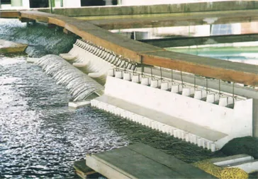
In order to verify these aspects, two hydraulic models were used, as presented in Chapter 10 (three-dimensional and two-dimensional models, as shown in Figures 1.2 and 1.3).
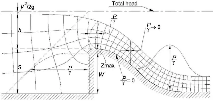
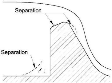
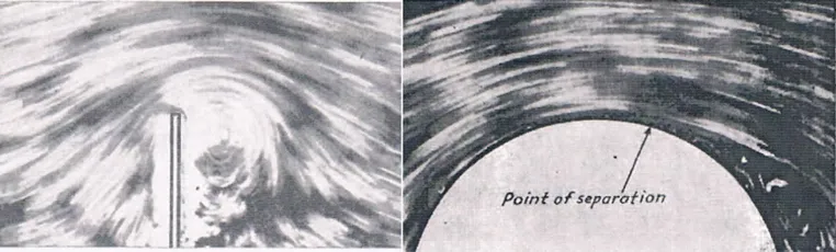
Figure 1.4 shows a typical flow net; Figures 1.5 and 1.6 show details of flow separation zones.
Figure 1.2 Tucuruí HPP (Brazil). Partial view of the three-dimensional model (scale 1:150).
Figure 1.3 Tucuruí spillway. Two-dimensional model (scale 1:50). It is worth noting the good performance of the flownet over the spillway (Q = 100.000 m3/s).
Figure 1.4 Typical flownet.
Source: (Rouse, 1938, 1950).
Figure 1.5 Separation zones of the flow – sketch.
Figure 1.6 Pattern of flow on a plate and on a cylinder.
Source: Images (Rouse, 1938, 1950).
According to Brater and King (1976), a spillway is a notch through which water flows; it may be a depression on the side of a tank or along the contour of a reservoir or channel, or may be a spillway dam or other similar structure.
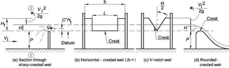
Classified in accordance with the shape of the notch, there are rectangular, triangular (or V-notch), trapezoidal and parabolic spillways (Figure 1.7).
The edge or surface over which the water flows is called the crest of the spillway. The over-flowing sheet of water is termed the nappe. The depth of water producing the discharge, H, is the head.
Figure 1.7 Spillways definition sketch.
Source: (Brater and King, 1976).
The main parameters are:
Httotal head (m);
H hydraulic head (m) ⇨ Q = c L H1, 5 (m3/s), as will be seen in Chapter 3;
V1velocity in the approach channel (m/s);
V velocity over the crest (m/s);
P crest height (m), parameter that strongly influences the discharge coefficient (c);
α1kinetic energy correction factor ≈ 1,0.
Sharp-crested weirs are useful only as a means of measuring flowing water. Spillways not sharp-crested are commonly incorporated in ...
Table of contents
Cover
Half Title
Title
Copyright
Dedication
Contents
Preface
Acknowledgments
About the author
List of acronyms
List of symbols
1 Introduction
2 Types of spillways
3 Spillway design
4 Hydrodynamics pressures
5 Energy dissipation
6 Pressure forces downstream of dissipators
7 Evaluation of the scour
8 Cavitation
9 Gates and valves
10 Hydraulic models
11 Specific constructive aspects of hydraulic surfaces
References
Appendix 1 Spillways deterioration and rehabilitation
Appendix 2 Overflow dams
Index
Frequently asked questions
Yes, you can cancel anytime from the Subscription tab in your account settings on the Perlego website. Your subscription will stay active until the end of your current billing period. Learn how to cancel your subscription
No, books cannot be downloaded as external files, such as PDFs, for use outside of Perlego. However, you can download books within the Perlego app for offline reading on mobile or tablet. Learn how to download books offline
Perlego offers two plans: Essential and Complete
Essential is ideal for learners and professionals who enjoy exploring a wide range of subjects. Access the Essential Library with 800,000+ trusted titles and best-sellers across business, personal growth, and the humanities. Includes unlimited reading time and Standard Read Aloud voice.
Complete: Perfect for advanced learners and researchers needing full, unrestricted access. Unlock 1.5M+ books across hundreds of subjects, including academic and specialized titles. The Complete Plan also includes advanced features like Premium Read Aloud and Research Assistant.
Both plans are available with monthly, semester, or annual billing cycles.
We are an online textbook subscription service, where you can get access to an entire online library for less than the price of a single book per month. With over 1.5 million books across 990+ topics, we’ve got you covered! Learn about our mission
Look out for the read-aloud symbol on your next book to see if you can listen to it. The read-aloud tool reads text aloud for you, highlighting the text as it is being read. You can pause it, speed it up and slow it down. Learn more about Read Aloud
Yes! You can use the Perlego app on both iOS and Android devices to read anytime, anywhere — even offline. Perfect for commutes or when you’re on the go. Please note we cannot support devices running on iOS 13 and Android 7 or earlier. Learn more about using the app
Yes, you can access Spillway Design - Step by Step by Geraldo Magela Pereira in PDF and/or ePUB format, as well as other popular books in Technologie et ingénierie & Énergie. We have over 1.5 million books available in our catalogue for you to explore.