Introduction
Let us start off with something that is really quite simple and yet is capable of producing a sense of real satisfaction when complete – a real medium-wave (MW) radio receiver! It proves that receivers can be simple and, at the same time, be useful and enjoyable to make. To minimise the confusion to absolute beginners, no circuit diagram is given, only the constructional details. The circuits will come later, when you have become accustomed to the building process. In the true amateur spirit of ingenuity and inventiveness, the circuit is built on a terminal strip, the coil is wound on a toilet roll tube (as amateur MW coils have been for 100 years!), and the receiver is mounted on a piece of wood.
Putting it together
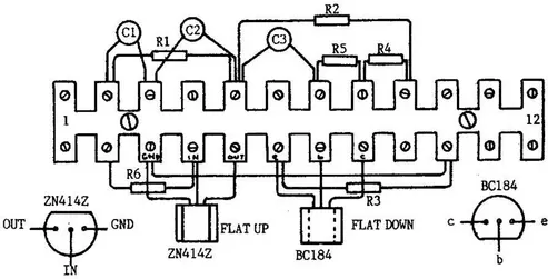
Start by mounting the components on the terminal strip as shown in Figure 1, carefully checking the position and value of each one. The three capacitors are all the same, and so present no problem. They (and the resistors) may be connected either way round, unlike the two semiconductors (see later). The resistors are coded by means of coloured bands. You can refer to Chapter 7 if you have difficulty remembering the colours and their values.
Figure 1 Terminal strip – position of components
| 1. Brown, Black, Yellow | 100 000 ohms | (R1, R5, R6) |
| 2. Green, Blue, Brown | 560 ohms | (R2) |
| 3. Red, Violet, Brown | 270 ohms | (R3) |
| 4. Brown, Black, Orange | 10 000 ohms | (R4) |
The integrated circuit (the ZN414Z) and the transistor (the BC184) must be connected correctly. Check Figure 1 carefully before fitting each device.
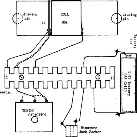
Now wind the coil. Most tubes are about 42 mm diameter and 110 mm long. Don’t worry if your tube is slightly different; it shouldn’t matter. Make two holes, about 3 mm apart, about 40 mm from one end, as shown in Figure 2. Loop your enamelled wire into one hole and out of the other, and draw about 100 mm through; loop this 100 mm through again, thus anchoring the wire firmly. Now wind on 80 turns, keeping the wire tight and the turns close together but not overlapping. After your 80th turn, make another two holes and anchor the wire in the same way as before. Again, leave about 100 mm free after anchoring. Using another piece of enamelled wire (with 100 mm ends as before), loop one end through the same two holes which contain the end anchor of the last winding, wind two turns and anchor the end of this short winding using another pair of holes. Figure 2 shows the layout.
Figure 2 The layout of the parts on the wooden base
With some glass paper, remove the enamel from the ends of both pieces of wire which go through the same holes (i.e. the bottom of the large coil and the top of the small coil), then twist these bare ends together. Remove the enamel from the remaining ends of the coil. The coil is now finished!
The baseboard can be any piece of wood about 150 mm square. Fix the coil near the back edge using drawing pins and connect the wires from the coils to the terminal strip as shown in Figure 2. Using short pieces of PVC-insulated wire (and with assistance if you have never soldered before), solder one piece across the two outer tags of the variable capacitor, shown by the dotted line in Figure 2, and then two longer pieces to the centre tag and one outside tag. Connect these to the terminal strip. Then solder two more insulated wires on to the jack socket (into which you will plug your crystal earpiece), the other ends going to the terminal strip. The last two wires (one must be red) need to be soldered on to the battery box, their other ends going to the terminal strip also. Make sure the red wire goes to the positive terminal on the battery, and is connected to terminal 9. The other connection to the battery goes to terminal 10.
Attach the terminal strip t...