![]()
CHAPTER 1
INTRODUCTION
1.1 Electromagnetic Compatibility at Component Level
Component manufacturers are not only exempt from the European electromagnetic compatibility (EMC) directive, but it is actually illegal for them to mark their components with a CE mark claiming compliance with this directive. Similarly, in the USA the Federal Communications Commission (FCC) make no mention of individual component compliance. So why bother looking at the EMC of components?
There are several possible answers depending on your position in the argument. First, for a component supplier it is beneficial to offer an advantage over the competition, it is also possible to charge more for a component with known EMC performance than for one without. Although EMC compliance of components is not a mandatory requirement today, this situation may change and those with measured EMC performance will have a head start. Of course customers may require knowledge of component EMC performance and require data whether it is mandatory or not.
As a consumer of electronic components it is of benefit to know how a part will behave regarding EMC in a system. In the long term it would obviously be preferable to pass any test or performance requirements as far down the electronic food chain as possible (i.e. to the component supplier). In the case where a problem is found, knowing the potential source of the problem can be half-way to fixing it; therefore, the EMC performance of components can be used to trace and eliminate overall circuit or system EMC performance problems.
So whether a supplier or consumer it is beneficial to know the EMC performance and have guidelines on the application of components with regards to EMC. The benefits are both technical and commercial, there is not only a requirement for suppliers to provide the data, but also for consumers to request the relevant data for their application.
The main concern with EMC at component level is the onset of non-ideal behaviour; for example, a capacitor is no longer capacitive above a certain frequency, but resistive or inductive. In general the areas of interest tend to occur at high frequencies, outside the functional operating frequency range of the component. It is operation outside of the functional frequency range due to conducted or radiated electromagnetic interference (EMI) that is the concern of this book. The effects may not be covered by the manufacturer as it is outside the recommended operation; unfortunately, EMI cannot read the data sheet recommendations. Operation in the high frequency area is often outside the applications’ information and even outside the experience of many component manufacturers.
1.2 EMC on the Printed Circuit Board
Almost every printed circuit board (PCB) is different and completely application specific. Even within similar products the PCB can be different, for example open two PCs from different manufacturers, with the same processor, clock speed, keyboard interface, etc., the actual PCB layout will be different. This diversity means that every PCB has a unique level of EMC performance, so what can possibly be done to ensure that this is within certain limits?
It should not surprise circuit designers that the layout of the PCB can have a significant effect on the EMC performance of a system, usually more so than the actual choice of components. Consequently, PCB layout is one of the most critical areas of consideration for design to meet EMC regulations.
The fact that there are so many different PCB designs in existence is a testimony to the low cost of producing a PCB, but relaying a complete PCB because of poor layout design causes significant increases in costs not present in the actual material price of the board. Relaying a PCB will create a delay in time to market, hence lost sales revenue. New PCB layouts or changes usually entail new solder masks, reprogramming component placement machines, rewriting the production instructions, etc., hence cost may not be present in the final product part cost, but in the development and production overhead.
Although a significant factor in overall EMC performance, the recommendations for minimising the effect of PCB layout on EMC are general good PCB design practices. The cost of implementing these recommendations is solely in the time taken to ensure that these good design practices are implemented, vigilance and experience are the two main requirements, not necessarily new design software or extensive retraining.
1.3 Parameters Relating to EMC Performance
It is well documented in several other texts on EMC that the parameter which need to be examined are: frequency, amplitude, time, impedance and dimensions. This is sometimes abbreviated to FATID, usually pronounced ‘fatted’, as in bringing the fatted calf to the slaughter (apologies to any vegetarians reading this).
In components it tends to be frequency, amplitude and impedance that dominate the interest. Usually, the frequency outside the normal range of operation and how much these signals are being attenuated (impeded). Examination of the amplitude of signal required to operate a device is also useful, generally devices with a higher operating threshold have higher immunity than those with low amplitude operating points.
With a PCB it is usually the frequency and physical dimensions that are the dominant parameters of interest. The advantage of a PCB is that as a designer we can exhibit full control over the physical dimensions, unlike with a component where the degrees of freedom are somewhat restricted. The physical dimensions of PCB tracks and interconnect effect the frequencies which the circuit will be susceptible to and which it can radiate best.
The time parameters can be converted to a frequency if the signal is continuous, or if it is the timing of edges that is causing a problem. The other time-dependent effect is determining if the problem is caused by a specific timed action within the circuit or system (e.g. switch action such as energising a relay). It is much more common in EMC to deal with frequency than time and examine signals in the frequency domain.
1.4 What’s In It For Me?
It cannot be guaranteed that in following all the design and component suggestions made in this book that every design will pass through EMC testing first time; however, by following the ideas postulated here the chances should be improved. It could be argued that not all the ideas are feasible together and I would not want to make anyone think that they had to follow all these suggestions to achieve EMC compliance. By careful use of some of the ideas, as and when appropriate, and by experience in applying them to your circuit designs, I am confident that the reader of this book will realise better EMC performance from their circuits at virtually no additional cost.
What all readers of this book should be able to achieve is that their circuits are optimised for EMC performance by following best design practices. They should have a better understanding of potential sources of EMC problems in existing circuits and have some idea of how to fix them. The reader should be armed with a design tool kit that allows them to produce the best EMC performance in the most cost-effective manner with the minimum requirements for post-layout add-ons such as mains filtering and shielding.
1.5 Summary
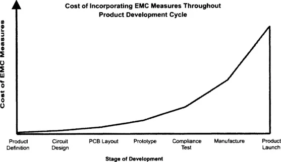
The most cost-effective way of complying with any requirements in a circuit, system or end product is to consider the requirements at the earliest stages of design (Figure 1.1). The aim of this book is to take the focus for EMC all the way down the electronics food chain to the component and PCB level. Designers should be aware at the outset of their design on how the choice of component type and placement of components will affect the EMC of their final circuit, as well as what additional protection may be required. This is of course supplementary to the circuits initial requirement of functional performance.
Figure 1.1 Cost of EMC measures
All component suppliers are exempt from the EU EMC directive and FCC regulations and, therefore, have no legal obligation to demonstrate compliance or issue EMC information. The more enlightened component supplier will already have some information and should be able to help advise of application pitfalls or give guidelines for EMC considerations. Do not be afraid to ask, the more this requirement is asked of suppliers the more likely they are to supply the information.
One problem many suppliers of components and their customers alike have is knowing what information would be useful. The application areas for a resistor, for example, are so diverse as to defy a general statement on ‘best’ method of application. If you know what information you would like to see get in touch with your component supplier, they may not be able to provide it immediately but by informing the component supplier of the need for certain information should see this eventually being included in the data sheet. Similarly, if one supplier can give you the data whereas another cannot, or will not, this could be a suitable method for reducing vendor selection or changing vendor ratings (e.g. if the impedance analysis of a network transformer is not given by one supplier, but is shown to be suitable by another, why risk a possible EMC problem).
PCB suppliers are a little bit more cognisant with regards to EMC. It has been known for a long time that the layout of a circuit is one of the major influences in the end circuits’ noise performance, hence its EMC performance. Even with the increased awareness there are still few suppliers who can offer tightly controlled impedance characteristics. Again there are no legislative obligations on the PCB supplier to provide a quiet PCB and it is ultimately the responsibility of the PCB designer or layout engineer.
It is unlikely that EMC will be the primary concern when first choosing components for a circuit design or when producing a PCB layout. If the advice given here is kept in mind, however, the possibility of poor component choice or PCB layout causing EMC problems should be minimised. After all, EMC begins and ends at the circuit level.
![]()
CHAPTER 2
PASSIVE COMPONENTS
The selection of passive component elements in a circuit is often overlooked as these components are usually chosen to bias or complement their more exciting active component counterparts. The passive component does have a significant ...