- 992 pages
- English
- ePUB (mobile friendly)
- Available on iOS & Android
eBook - ePub
J & P Transformer Book
About this book
Maintaining appropriate power systems and equipment expertise is necessary for a utility to support the reliability, availability, and quality of service goals demanded by energy consumers now and into the future. However, transformer talent is at a premium today, and all aspects of the power industry are suffering a diminishing of the supply of knowledgeable and experienced engineers.Now in print for over 80 years since initial publication in 1925 by Johnson & Phillips Ltd, the J & P Transformer Book continues to withstand the test of time as a key body of reference material for students, teachers, and all whose careers are involved in the engineering processes associated with power delivery, and particularly with transformer design, manufacture, testing, procurement, application, operation, maintenance, condition assessment and life extension.Current experience and knowledge have been brought into this thirteenth edition with discussions on moisture equilibrium in the insulation system, vegetable based natural ester insulating fluids, industry concerns with corrosive sulphur in oil, geomagnetic induced current (GIC) impacts, transportation issues, new emphasis on measurement of load related noise, and enhanced treatment of dielectric testing (including Frequency Response Analysis), Dissolved Gas analysis (DGA) techniques and tools, vacuum LTCs, shunt and series reactors, and HVDC converter transformers. These changes in the thirteenth edition together with updates of IEC reference Standards documentation and inclusion for the first time of IEEE reference Standards, provide recognition that the transformer industry and market is truly global in scale. -- From the foreword by Donald J. FallonMartin Heathcote is a consultant specializing in power transformers, primarily working for utilities. In this context he has established working relationships with transformer manufacturers on several continents. His background with Ferranti and the UK's Central Electricity Generating Board (CEGB) included transformer design and the management and maintenance of transformer-based systems.* The definitive reference for all involved in designing, installing, monitoring and maintaining high-voltage systems using power transformers (electricity generation and distribution sector; large-scale industrial applications)* The classic reference work on power transformers and their applications: first published in 1925, now brought fully up to date in this thirteenth edition* A truly practical engineering approach to design, monitoring and maintenance of power transformers – in electricity generation, substations, and industrial applications.
Trusted by 375,005 students
Access to over 1 million titles for a fair monthly price.
Study more efficiently using our study tools.
Information
1 Transformer theory
1.1 INTRODUCTION
The invention of the power transformer towards the end of the nineteenth century made possible the development of the modern constant voltage AC supply system, with power stations often located many miles from centres of electrical load. Before that, in the early days of public electricity supplies, these were DC systems with the source of generation, of necessity, close to the point of loading.
Pioneers of the electricity supply industry were quick to recognise the benefits of a device which could take the high current relatively low voltage output of an electrical generator and transform this to a voltage level which would enable it to be transmitted in a cable of practical dimensions to consumers who, at that time, might be a mile or more away and could do this with an efficiency which, by the standards of the time, was nothing less than phenomenal.
Todays transmission and distribution systems are, of course, vastly more extensive and greatly dependent on transformers which themselves are very much more efficient than those of a century ago; from the enormous generator transformers such as the one illustrated in Fig. 7.5, stepping up the output of up to 19 000 A at 23.5 kV, of a large generating unit in the UK, to 400 kV, thereby reducing the current to a more manageable 1200 A or so, to the thousands of small distribution units which operate almost continuously day in day out, with little or no attention, to provide supplies to industrial and domestic consumers.
The main purpose of this book is to examine the current state of transformer technology, inevitably from a UK viewpoint, but in the rapidly shrinking and ever more competitive world of technology it is not possible to retain one’s place in it without a knowledge of all that is going on the other side of the globe, so the viewpoint will, hopefully, not be an entirely parochial one.
For a reasonable understanding of the subject it is necessary to make a brief review of transformer theory together with the basic formulae and simple phasor diagrams.
1.2 THE IDEAL TRANSFORMER: VOLTAGE RATIO
A power transformer normally consists of a pair of windings, primary and secondary, linked by a magnetic circuit or core. When an alternating voltage is applied to one of these windings, generally by definition the primary, a current will flow which sets up an alternating m.m.f. and hence an alternating flux in the core. This alternating flux in linking both windings induces an e.m.f. in each of them. In the primary winding this is the ‘back-e.m.f’ and, if the transformer were perfect, it would oppose the primary applied voltage to the extent that no current would flow. In reality, the current which flows is the transformer magnetising current. In the secondary winding the induced e.m.f. is the secondary open-circuit voltage. If a load is connected to the secondary winding which permits the flow of secondary current, then this current creates a demagnetising m.m.f. thus destroying the balance between primary applied voltage and back-e.m.f. To restore the balance an increased primary current must be drawn from the supply to provide an exactly equivalent m.m.f. so that equilibrium is once more established when this additional primary current creates ampere-turns balance with those of the secondary. Since there is no difference between the voltage induced in a single turn whether it is part of either the primary or the secondary winding, then the total voltage induced in each of the windings by the common flux must be proportional to the number of turns. Thus the well-known relationship is established that:

and, in view of the need for ampere-turns balance:

where E, I and N are the induced voltages, the currents and number of turns respectively in the windings identified by the appropriate subscripts. Hence, the voltage is transformed in proportion to the number of turns in the respective windings and the currents are in inverse proportion (and the relationship holds true for both instantaneous and r.m.s. quantities).
The relationship between the induced voltage and the flux is given by reference to Faraday’s law which states that its magnitude is proportional to the rate of change of flux linkage and Lenz’s law which states that its polarity such as to oppose that flux linkage change if current were allowed to flow. This is normally expressed in the form
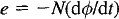
but, for the practical transformer, it can be shown that the voltage induced per turn is

where K is a constant, Φm is the maximum value of total flux in Webers linking that turn and f is the supply frequency in Hertz.
The above expression holds good for the voltage induced in either primary or secondary windings, and it is only a matter of inserting the correct value of N for the winding under consideration. Figure 1.1 shows the simple phasor diagram corresponding to a transformer on no-load (neglecting for the moment the fact that the transformer has reactance) and the symbols have the significance shown on the diagram. Usually in the practical design of transformer, the small drop in voltage due to the flow of the no-load current in the primary winding is neglected.
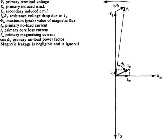
Figure 1.1 Phasor diagram for a single-phase transformer on open circuit. Assumed turns ratio 1:1
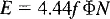
If the voltage is sinusoidal, which, of course, is always assumed, K is 4.44 and Eq. (1.3) becomes
For design calculations the designer is more interested in volts per turn and flux density in the core rather than total flux, so t...
Table of contents
- Cover
- Title Page
- Foreword
- Preface to the thirteenth edition
- Acknowledgements
- Table of Contents
- Chapter 1: Transformer theory
- Chapter 2: Design fundamentals
- Chapter 3: Basic materials
- Chapter 4: Transformer construction
- Chapter 5: Testing of transformers
- Chapter 6: Operation and maintenance
- Chapter 7: Special features of transformers for particular purposes
- Chapter 8: Transformer enquiries and tenders
- Appendix 1: Transformer equivalent circuit
- Appendix 2: Geometry of the transformer phasor diagram
- Appendix 3: The transformer circle diagram
- Appendix 4: Transformer regulation
- Appendix 5: Symmetrical components in unbalanced three-phase systems
- Appendix 6: A symmetrical component study of earth faults in transformers in parallel
- Appendix 7: The use of finite-element analysis in the calculation of leakage flux and dielectric stress distributions
- Appendix 8: List of national and international standards relating to power transformers
- Appendix 9: List of principal CIGRE reports and papers relating to transformers
- Appendix 10: List of reports available from ERA Technology Ltd
- Index
- Instructions for online access
Frequently asked questions
Yes, you can cancel anytime from the Subscription tab in your account settings on the Perlego website. Your subscription will stay active until the end of your current billing period. Learn how to cancel your subscription
No, books cannot be downloaded as external files, such as PDFs, for use outside of Perlego. However, you can download books within the Perlego app for offline reading on mobile or tablet. Learn how to download books offline
Perlego offers two plans: Essential and Complete
- Essential is ideal for learners and professionals who enjoy exploring a wide range of subjects. Access the Essential Library with 800,000+ trusted titles and best-sellers across business, personal growth, and the humanities. Includes unlimited reading time and Standard Read Aloud voice.
- Complete: Perfect for advanced learners and researchers needing full, unrestricted access. Unlock 1.4M+ books across hundreds of subjects, including academic and specialized titles. The Complete Plan also includes advanced features like Premium Read Aloud and Research Assistant.
We are an online textbook subscription service, where you can get access to an entire online library for less than the price of a single book per month. With over 1 million books across 990+ topics, we’ve got you covered! Learn about our mission
Look out for the read-aloud symbol on your next book to see if you can listen to it. The read-aloud tool reads text aloud for you, highlighting the text as it is being read. You can pause it, speed it up and slow it down. Learn more about Read Aloud
Yes! You can use the Perlego app on both iOS and Android devices to read anytime, anywhere — even offline. Perfect for commutes or when you’re on the go.
Please note we cannot support devices running on iOS 13 and Android 7 or earlier. Learn more about using the app
Please note we cannot support devices running on iOS 13 and Android 7 or earlier. Learn more about using the app
Yes, you can access J & P Transformer Book by Martin Heathcote in PDF and/or ePUB format, as well as other popular books in Technology & Engineering & Electrical Engineering & Telecommunications. We have over one million books available in our catalogue for you to explore.