- 768 pages
- English
- ePUB (mobile friendly)
- Available on iOS & Android
eBook - ePub
Switching Power Supplies A - Z
About this book
Switching Power Supplies A - Z is the most comprehensive study available of the theoretical and practical aspects of controlling and measuring Electromagnetic Interference in switching power supplies, including input filter instability considerations.
The new edition is thoroughly revised with six completely new chapters, while the existing EMI chapters are expanded to include many more step-by-step numerical examples and key derivations and EMI mitigation techniques. New topics cover the length and breadth of modern switching power conversion techniques, lucidly explained in simple but thorough terms, now with uniquely detailed "wall-reference charts" providing easy access to even complex topics.
- Step-by-step and iterative approach for calculating high-frequency losses in forward converter transformers, including Proximity losses based on Dowell's equations
- Thorough, yet uniquely simple design flow-chart for building DC-DC converters and their magnetic components under typical wide-input supply conditions
- Step-by-step, solved examples for stabilizing control loops of all three major topologies, using either transconductance or conventional operational amplifiers, and either current-mode or voltage-mode control
Trusted by 375,005 students
Access to over 1.5 million titles for a fair monthly price.
Study more efficiently using our study tools.
Information
Chapter 1
The Principles of Switching Power Conversion
This is the entry point into the field of switching power conversion. It starts from the very basics: the charging and discharging of a capacitor and attempts to develop a parallel intuition for the way an inductor behaves when it is carrying current. Replete with real-world analogies, it shows the importance of providing a freewheeling path for the inductor current. That angle of approach eventually leads to the evolution of switching topologies. It also becomes very clear why there are only three fundamental topologies. The voltseconds law in steady state is explained and how that leads to the underlying DC transfer function. Basic converter operation including continuous and discontinuous conduction modes is also discussed.
Introduction
Imagine we are at some busy “metro” terminus one evening at peak hour. Almost instantly, thousands of commuters swarm the station trying to make their way home. Of course, there is no train big enough to carry all of them simultaneously. So, what do we do? Simple! We split this sea of humanity into several trainloads — and move them out in rapid succession. Many of these outbound passengers will later transfer to alternative forms of transport. So, for example, trainloads may turn into bus-loads or taxi-loads, and so on. But eventually, all these “packets” will merge once again, and a throng will be seen, exiting at the destination.
Switching power conversion is remarkably similar to a mass transit system. The difference is that instead of people, it is energy that gets transferred from one level to another. So we draw energy continuously from an “input source,” chop this incoming stream into packets by means of a “switch” (a transistor), and then transfer it with the help of components (inductors and capacitors) that are able to accommodate these energy packets and exchange them among themselves as required. Finally, we make all these packets merge again and thereby get a smooth and steady flow of energy into the output.
So, in either of the cases above (energy or people), from the viewpoint of an observer, a stream will be seen entering and a similar one exiting. But at an intermediate stage, the transference is accomplished by breaking up this stream into more manageable packets.
Looking more closely at the train station analogy, we also realize that to be able to transfer a given number of passengers in a given time (note that in electrical engineering, energy transferred in unit time is “power”) — either we need bigger trains with departure times spaced relatively far apart OR several smaller trains leaving in rapid succession. Therefore, it should come as no surprise that in switching power conversion, we always try to switch at high frequencies. The primary purpose for that is to reduce the size of the energy packets and thereby also the size of the components required to store and transport them.
Power supplies that use this principle are called “switching power supplies” or “switching power converters.”
“DC–DC converters” are the basic building blocks of modern high-frequency switching power supplies. As their name suggests, they “convert” an available DC (direct current) input voltage rail “VIN” to another more desirable or usable DC output voltage level “VO.” “AC–DC converters” (see Figure 1.1), also called “off-line power supplies,” typically run off the mains input (or “line input”). But they first rectify the incoming sinusoidal AC (alternating current) voltage “VAC” to a DC voltage level (often called the “HVDC rail” or “high voltage DC rail”) — which then gets applied at the input of what is essentially just another DC–DC converter stage (or derivative thereof). We thus see that power conversion is, in essence, almost always a DC–DC voltage conversion process.

Figure 1.1: Typical off-line power supply.
But it is also equally important to create a steady DC output voltage level, from what can often be a widely varying and different DC input voltage level. Therefore, a “control circuit” is used in all power converters to constantly monitor and compare the output voltage against an internal “reference voltage.” Corrective action is taken if the output drifts from its set value. This process is called “output regulation” or simply “regulation.” Hence, the generic term “voltage regulator” for supplies which can achieve this function, switching, or otherwise.
In a practical implementation, “application conditions” are considered to be the applied input voltage VIN (also called the “line voltage”), the current being drawn at the output, that is, IO (the “load current”), and the set output voltage VO. Temperature is also an application condition, but we will ignore it for now, since its effect on the system is usually not so dramatic. Therefore, for a given output voltage, there are two specific application conditions whose variations can cause the output voltage to be immediately impacted (were it not for the control circuit). Maintaining the output voltage steady when VIN varies over its stated operating range VINMIN to VINMAX (minimum input to maximum input) is called “line regulation,” whereas maintaining regulation when IO varies over its operating range IOMIN to IOMAX (minimum-to-maximum load) is referred to as “load regulation.” Of course, nothing is ever “perfect,” so nor is the regulation. Therefore, despite the correction, there is a small but measurable change in the output voltage, which we call “ΔVO” here. Note that mathematically, line regulation is expressed as “ΔVO/VO×100% (implicitly implying it is over VINMIN to VINMAX).” Load regulation is similarly “ΔVO/VO×100%” (from IOMIN to IOMAX).
However, the rate at which the output can be corrected by the power supply (under sudden changes in line and load) is also important — since no physical process is “instantaneous.” So, the property of any converter to provide quick regulation (correction) under external disturbances is referred to as its “loop response” or “AC response.” Clearly, the loop response is in general, a combination of “step-load response” and “line transient response.”
As we move on, we will first introduce the reader to some of the most basic terminology of power conversion and its key concerns. Later, we will progress toward understanding the behavior of the most vital component of power conversion — the inductor. It is this component that even some relatively experienced power designers still have trouble with! Clearly, real progress in any area cannot occur without a clear understanding of the components and the basic concepts involved. Therefore, only after understanding the inductor well enough, can we go on to demonstrate the fact that switching converters are not all that mysterious either — in fact they evolve quite naturally out of a keen understanding of the inductor.
Overview and Basic Terminology
Efficiency
Any regulator carries out the process of power conversion with an “efficiency,” defined as

where PO is the “output power,” equal to

and PIN is the “input power,” equal to

Here, IIN is the average or DC current being drawn from the source.
Ideally we want η=1, and that would represent a “perfect” conversion efficiency of 100%. But in a real converter, that is, with η<1, the difference “PIN−PO” is simply the wasted power “Ploss” or “dissipation” (occurring within the converter itself). By simple manipulation, we get


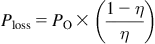
This is the loss expressed in terms of the output power. In terms of the input power, we would similarly get

The loss manifests itself as heat in the converter, which in turn causes a certain measurable “temperature rise” ΔΤ over the surrounding “room temperature” (or “ambient temperature”). Note that high temperatures affect the reliability of all systems — the rule of thumb being that every 10°C rise causes the failure rate to double. Therefore, part of our skill as designers is to reduce this temperature rise and also achieve higher efficiencies.
Coming to the input current (drawn by the converter), for the hypothetical case of 100% efficiency, we get

So, in a real converter, the input current increases from its “ideal” value by the factor 1/η.

Therefore, if we can achieve high efficiency, the current drawn from the input (keeping application conditions unchanged) will decrease — but only up to a point. The input current clearly canno...
Table of contents
- Cover Image
- Contents
- Title
- Copyright
- Preface
- Acknowledgments
- Chapter 1. The Principles of Switching Power Conversion
- Chapter 2. DC–DC Converter Design and Magnetics
- Chapter 3. Off-Line Converter Design and Magnetics
- Chapter 4. The Topology FAQ
- Chapter 5. Advanced Magnetics
- Chapter 6. Component Ratings, Stresses, Reliability, and Life
- Chapter 7. Optimal Power Components Selection
- Chapter 8. Conduction and Switching Losses
- Chapter 9. Discovering New Topologies
- Chapter 10. Printed Circuit Board Layout
- Chapter 11. Thermal Management
- Chapter 12. Feedback Loop Analysis and Stability
- Chapter 13. Advanced Topics
- Chapter 14. The Front End of AC–DC Power Supplies
- Chapter 15. EMI Standards and Measurements
- Chapter 16. Practical EMI Line Filters and Noise Sources in Power Supplies
- Chapter 17. Fixing EMI Across the Board and Input Filter Instability
- Chapter 18. The Math Behind the Electromagnetic Puzzle
- Chapter 19. Solved Examples
- Appendix
- Index
Frequently asked questions
Yes, you can cancel anytime from the Subscription tab in your account settings on the Perlego website. Your subscription will stay active until the end of your current billing period. Learn how to cancel your subscription
No, books cannot be downloaded as external files, such as PDFs, for use outside of Perlego. However, you can download books within the Perlego app for offline reading on mobile or tablet. Learn how to download books offline
Perlego offers two plans: Essential and Complete
- Essential is ideal for learners and professionals who enjoy exploring a wide range of subjects. Access the Essential Library with 800,000+ trusted titles and best-sellers across business, personal growth, and the humanities. Includes unlimited reading time and Standard Read Aloud voice.
- Complete: Perfect for advanced learners and researchers needing full, unrestricted access. Unlock 1.5M+ books across hundreds of subjects, including academic and specialized titles. The Complete Plan also includes advanced features like Premium Read Aloud and Research Assistant.
We are an online textbook subscription service, where you can get access to an entire online library for less than the price of a single book per month. With over 1.5 million books across 990+ topics, we’ve got you covered! Learn about our mission
Look out for the read-aloud symbol on your next book to see if you can listen to it. The read-aloud tool reads text aloud for you, highlighting the text as it is being read. You can pause it, speed it up and slow it down. Learn more about Read Aloud
Yes! You can use the Perlego app on both iOS and Android devices to read anytime, anywhere — even offline. Perfect for commutes or when you’re on the go.
Please note we cannot support devices running on iOS 13 and Android 7 or earlier. Learn more about using the app
Please note we cannot support devices running on iOS 13 and Android 7 or earlier. Learn more about using the app
Yes, you can access Switching Power Supplies A - Z by Sanjaya Maniktala in PDF and/or ePUB format, as well as other popular books in Technology & Engineering & Electrical Engineering & Telecommunications. We have over 1.5 million books available in our catalogue for you to explore.