eBook - ePub
A Guide to Motor Boat Design and Construction - A Collection of Historical Articles Containing Information on the Methods and Equipment of the Boat Builder
- 174 pages
- English
- ePUB (mobile friendly)
- Available on iOS & Android
eBook - ePub
A Guide to Motor Boat Design and Construction - A Collection of Historical Articles Containing Information on the Methods and Equipment of the Boat Builder
About this book
This volume contains a collection of classic articles on the subject of designing and building motor boats, with information on equipment, methods, common problems, materials, where to begin, installing motors, and much more. Carefully selected for a modern readership, this timeless volume will be of considerable utility to anyone with a practical interest in boating or sailing, and would make for a fantastic addition to collections of related literature. The articles include: "Boat Building and Boating", "Canoeing, Sailing, and Motor Boating", "Motor Boating for All", "Popular Mechanics Build a Boat for Pleasure or Profit- Build your own Boat", and "The Motor Boat Manual – With a Special Section on Outboard Motors and Boats". Many vintage books such as this are becoming increasingly scarce and expensive. We are republishing this volume now in an affordable, high-quality edition complete with a specially commissioned new introduction on boat building.
Trusted by 375,005 students
Access to over 1.5 million titles for a fair monthly price.
Study more efficiently using our study tools.
Information
“FALCON”
TRIM, STURDY 18-FT. INBOARD
By Don B. Pedersen
Incorporating the latest developments in boat construction and eliminating many problems which usually confront the average novice in boat building, “Falcon” is an all-around utility run-about which can be transformed easily into a sleek cabin cruiser if desired. The cost of building the original boat as a runabout was $125 at Newport Beach, Calif. The hull is adapted for use of almost any marine engine from 5 to 20 hp. Total depth 16 in., beam 66 in., draft 42 in., passengers 7 or 8 and speed 17 m.p.h. with a 20 hp. motor. The boat planes at 7 m.p.h.
-plgo-compressed.webp)
PART I—BUILDING THE HULL
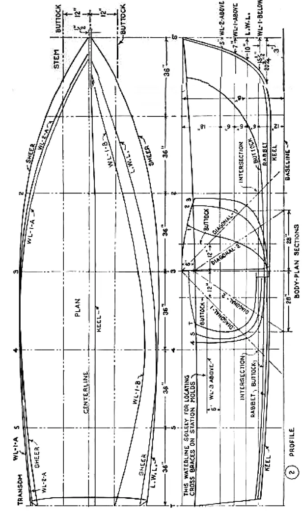
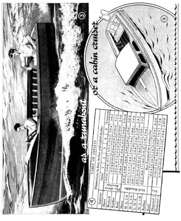
BEFORE starting actual construction on the hull, which is the same for either the runabout or cabin cruiser, Figs. 3 and 5, the plan, profile and the body sections Fig. 2 are drawn full size on two plywood panels placed end to end on the floor as in Fig. 6. A 1-in. strip added to the top edge of the panels will enable you to work from a baseline drawn 1/2 in. up from the bottom edge. Referring to Fig. 2, first mark off the vertical stations, which are spaced 36 in. apart. Then draw the five waterlines, the diagonals and finally the buttock lines. Use a thin batten to obtain a sweeping curve while an assistant does the marking. For the sake of clearness in the plan view, Fig. 2, some of the lines such as the sheer, WL-1-A and WL-2-A, are shown above the centerline, while others are below. However, in a full-size layout, all lines can be drawn above the centerline, making it necessary to draw but half of the plan. To explain how the table of offsets, Fig. 4, is used in determining the shape of the five molds, an example is given in Fig. 7 for finding the outline of station mold No. 3. In the offset table under “half breadths” you will note that the dimension at the sheer line is given as 2-9-0, which means 2 ft., 9 in. and no eighth inches. This distance is marked from the centerline on the plywood panel. Follow this method for the four waterlines, then the distances given for the diagonals. Next drive a nail at each mark and bend a thin batten around them to trace the curve, as shown in Fig. 10.
The simplest method to use in transferring the outlines directly to your mold material is to use nails in the manner shown in Figs. 12 and 13. To do this, arcs are scribed as in Fig. 11, using a compass set to equal the thickness of the planking which is 11/16 in. Now, following Fig. 12, shingle nails are set with their heads in the arcs, over which your mold stock is placed as shown in Fig. 13. Then, being careful not to disturb the position of the nails, apply your weight to make slight impressions on the underside of the work.
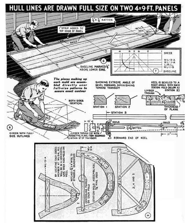
Drawing a line through the impressions just made, Fig. 14, gives a true outline of the station mold. Repeat this method for transferring the lower curve of the outline. Pieces comprising each mold are nailed together using blocks to straddle the joints as shown in Figs. 8 and 9. The horizontal braces of the molds are located on waterline WL.-3-A so that a longitudinal brace placed across the top of the former will be horizontal and perfectly level. Unless you intend to make several hulls from one set of molds, white pine will do. Otherwise hardwood should be used. Except for appearance, it is not necessary to curve the inside edges of the molds as shown.
The outline of the stem is transferred in the manner described for the molds, except that instead of being impressed directly upon the mahogany stem blank, plywood is used from which a pattern is cut and later used to trace the outline as in Fig. 16. The knee or anchor lock is outlined in the same manner. To lay out the rabbet and bearding lines on the stem, proceed with the nail-head method, working from the full-size outlines. Then a brad is driven through each indentation, the pattern is laid on the work and the nails are tapped through to make a prick mark on the stem. Both sides of the stem can be marked with the same plywood pattern by simply reversing the brads in the holes. See Fig. 16. Figs. 17, 18 and 19 detail the cutting of the planking rabbet. This is chiseled by hand and checked from time to time for the correct angle with a fid which is simply a small block the same thickness of the planking, Fig. 19. This angle at the sheer and waterlines can be taken from the plan lines on the floor. Sections of the stem are given in Fig. 15. Cuts are made at regular intervals along the rabbet and bearding lines and then the waste is removed between these notches to form a continuous rabbet as shown in Fig. 18. The stem is left extra long to allow for trimming to exact length at the sheer. Fig. 15 shows the relative positions of the stem, deadwood and keel with reference to station No. 1 and the waterlines. All three pieces are checked with the full-size floor plans as in Fig. 1, and are bolted together with four 8-in. brass bolts, the heads of which are ground flat to fit tightly in slots made in the cutwater or front edge of the stem. Also, two stopwaters are inserted where indicated. These are simply 3/8-in. white-pine dowels driven tightly in undersize holes. When these become wet, they swell to make a watertight joint.

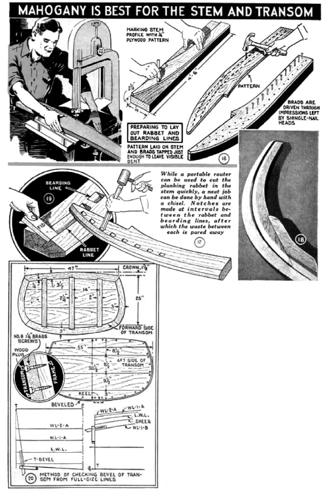
The keel is cut from a Douglas-fir plank 16 ft. long and is tapered from station No. 1 to where it meets the stem. This taper is marked with a batten as shown in the detail to the right of Fig. 9. A limber trough is made from the end of the deadwood to within 18 in. of the transom, to permit bilge to flow to the lowest point under the ribs. This can be cut by machine, or by hand with a rabbeting plane. Cutting the rabbet along the keel is simply a matter of planing a bevel, pronounced at the forward end and diminishing toward the transom at which point it becomes nil. It is most important that the plank for the keel be perfectly straight. If there is the slightest curve in it, it must be planed true. The transom frame is made of 3/4-in. thoroughly seasoned dark-red Philippine mahogany and covered with the widths of stock as specified in the upper detail of Fig. 20. The outline for this is taken from the full-size plans. The angle of the bevel varies, of course, and can be determined with the use of a sliding T-bevel as shown in Fig. 20. From the aft side, screws are used around the edge only, after which the heads are capped with wood plugs as shown in the circular detail. Those on the inside may be left exposed. Use marine or casein waterproof glue in assembling.
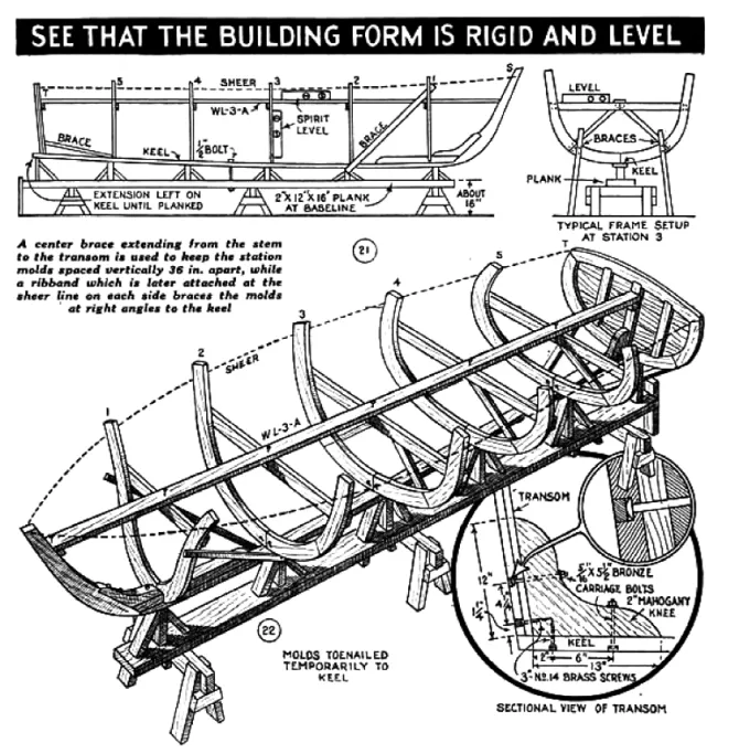
Constructing a building form that is square, true and rigid is as important as the work on the boat itself. Figs. 21 and 22 show how the form is assembled. This must be set up absolutely level. If set on the ground, be sure that it is placed on firm soil. Note the 2 by 4-in. braces under each station and the diagonal braces from No. 1 to No. 2 and from No. 5 to transom. The keel is bolted to the plank which later serves as a baseline. Use a spirit level and square to see that each mold is at right angles to the keel and absolutely vertical. The end view in Fig. 21 shows additional braces supporting each mold from the floor.
At this stage a knee must be installed at the base of the transom as shown in the circular detail of Fig. 22. Bolt and screw heads are countersunk and plugged, and clinch rings are used under the nuts on the inside. Like the knee at the stem, this should be fitted accurately, using casein waterproof glue. In squaring up the transom, a steel tapeline is run from the stem rabbet to the upper corner of the transom on one side and then the other side, and likewise on the bottom from station No. 5, as in Fig. 25. When all the molds have been properly squared and braced, a ribband is fitted below the sheer line on each side to hold each mold in its relative position. These ribbands are tapered toward the stem to make them bend easily. From stem to transom there are...
Table of contents
- A CHEAP AND SPEEDY MOTOR-BOAT
- MOTOR BOAT FITTINGS
- CONSTRUCTION OF THE HULL
- “HALF-PINT”
- BUILD “BANTA” — 12-FOOT PLYWOOD OUTBOARD
- “SKIPPER” —LOW-COST
- “FALCON”TRIM, STURDY 18-FT. INBOARD
- BOAT CONSTRUCTION. FIRST PRINCIPLES
- HULL DESIGN
- PRACTICAL DETAILS OF BOAT-BUILDING
- TYPICAL MOTOR CRAFT
- HIGH-SPEED MOTOR BOATS.REPRESENTATIVE TYPES OF HIGH-SPEED CRAFT
Frequently asked questions
Yes, you can cancel anytime from the Subscription tab in your account settings on the Perlego website. Your subscription will stay active until the end of your current billing period. Learn how to cancel your subscription
No, books cannot be downloaded as external files, such as PDFs, for use outside of Perlego. However, you can download books within the Perlego app for offline reading on mobile or tablet. Learn how to download books offline
Perlego offers two plans: Essential and Complete
- Essential is ideal for learners and professionals who enjoy exploring a wide range of subjects. Access the Essential Library with 800,000+ trusted titles and best-sellers across business, personal growth, and the humanities. Includes unlimited reading time and Standard Read Aloud voice.
- Complete: Perfect for advanced learners and researchers needing full, unrestricted access. Unlock 1.5M+ books across hundreds of subjects, including academic and specialized titles. The Complete Plan also includes advanced features like Premium Read Aloud and Research Assistant.
We are an online textbook subscription service, where you can get access to an entire online library for less than the price of a single book per month. With over 1.5 million books across 990+ topics, we’ve got you covered! Learn about our mission
Look out for the read-aloud symbol on your next book to see if you can listen to it. The read-aloud tool reads text aloud for you, highlighting the text as it is being read. You can pause it, speed it up and slow it down. Learn more about Read Aloud
Yes! You can use the Perlego app on both iOS and Android devices to read anytime, anywhere — even offline. Perfect for commutes or when you’re on the go.
Please note we cannot support devices running on iOS 13 and Android 7 or earlier. Learn more about using the app
Please note we cannot support devices running on iOS 13 and Android 7 or earlier. Learn more about using the app
Yes, you can access A Guide to Motor Boat Design and Construction - A Collection of Historical Articles Containing Information on the Methods and Equipment of the Boat Builder by Various in PDF and/or ePUB format, as well as other popular books in Technology & Engineering & Military Science & Technology. We have over 1.5 million books available in our catalogue for you to explore.