eBook - ePub
Principles of Fluoroscopic Image Intensification and Television Systems
Workbook and Laboratory Manual
- 252 pages
- English
- ePUB (mobile friendly)
- Available on iOS & Android
eBook - ePub
Principles of Fluoroscopic Image Intensification and Television Systems
Workbook and Laboratory Manual
About this book
This unique workbook can be used as a stand-alone text or supplemental text for any course designed to enhance the work of radiologic technology students. It will also serve the needs of graduate radiographers as well as the physician in learning specific areas of the Fluoroscopic Image Intensifier such as:
Tools to learn more effectively

Saving Books

Keyword Search

Annotating Text

Listen to it instead
Information
Chapter 1
Image Intensifier System
Objectives
Upon completion of Chapter 1, the reader will be able to:
1. Describe the basic parts of the image intensifier tube: input phosphor and photocathode, electrostatic lens, accelerating anode, and output phosphor.
2. Explain how to use a dual field image intensifier tube for magnification procedures.
3. Calculate the amount of patient exposure in the magnified mode.
4. Define conversion factor and brightness gain.
5. Calculate the minification ratio of the image intensifier tube.
6. Explain how image quality of the image intensifier tube is affected by scintillation, resolution, contrast, and distortion.
7. Describe the automatic brightness stabilizer system.
8. Recall the types of brightness sensing devices.
9. Identify the types of automatic brightness sensing circuits that are used with the x-ray generator.
Conventional fluoroscopy, without image intensification, has two serious limitations: it produces a statistically inferior image and one too dim for photopic (daylight) vision. In the early 1950s, the x-ray image intensifier was developed, which has revolutionized fluoroscopy. Its image is bright enough for scotopic vision and small enough to be conveniently coupled to cine, television, or spot-film cameras.
Image Intensifier Tube Design
The image intensifier tube is an evacuated glass envelope, a vacuum tube, which contains four basic parts (Figure 1.1):
1. Input phosphor and photocathode.
2. Electrostatic focusing lens.
3. Accelerating anode.
4. Output phosphor.
Input Phosphor and Photocathode
First-generation image intensifier tubes had silver-activated zinc cadmium sulfide crystals in the input screen. Second-generation intensifiers have cesium iodide (Csl) input screens. The fluorescent material is deposited on a thin substrate of the glass envelope. It serves the purpose of converting incident x-ray beam photons into a light image. The fluorescent screen and the photocathode are separated by a thin transparent layer only a fraction of a millimeter. Very little of the image is lost as the image is transferred from the screen to the photocathode.

The photocathode is a photo-emissive metal (usually a combination of antimony [Sb] and cesium [Cs] compounds). The photocathode receives the light emitted from the input screen and emits electrons in proportion to the intensity of the light it receives. One can appreciate the necessity of the input screen and photocathode being in very close proximity. Otherwise the image detail transmitted from one to the other would be significantly degraded. The photocathode also serves as the cathode of the image intensifier tube. It is kept at ground potential. By establishing a voltage or difference in electrical potential between the cathode and the accelerating anode, the electrons can be made to transverse the tube toward the output screen.
Electrostatic Focusing Lens
The focusing of electrons is accomplished by a series of rings called the electrostatic lenses, which are located inside the tube envelope and concentric with the tube axis. Applying a positive electrical potential difference to the electrostatic lens will cause the electrons emitted from the photocathode to be focused into an extremely fine beam. Each point on the input screen is focused to a specific point on the opposite side of the output screen. Electron focusing inverts the image on the output phosphor. The image on the output phosphor is reduced in size, which is one of the principal reasons why it is brighter.
Accelerating Anode
Located at the neck of the image intensifier tube, the accelerating anode draws electrons from the photocathode and accelerates them toward the output screen. The anode of a 6-in. image intensifier tube has a positive potential difference (voltage) of 25,000 volts (25 kVp), so it accelerates electrons to a tremendous velocity.
Output Phosphor
The output fluorescent screen of the 6-in. image intensifier tube is made from cesium iodide. The crystal size and layer thickness are reduced to maintain resolution in the minified image. Since the electrons are greatly accelerated, they emit more light photons from the output screen than were originally present in the input screen. The number of light photons is increased approximately 50 times. A thin layer of aluminum is plated onto the fluorescent screen to prevent light from moving retrograde through the tube and activating the photocathode. The aluminum layer is very thin, and high-energy photoelectrons easily pass through it en route to the output screen. This layer also serves as a ground to remove spent electrons from the image tube. If they were not removed, they would accumulate on the output phosphor and build up a negative charge.
The output screen is optically coupled to a viewing system by subjective lenses. The image is viewed either directly through a series of lenses and mirrors or indirectly through a closed circuit television system.
Dual Field Image Intensifier Tubes
Field size on the output phosphor is changed by applying a simple electronic principle: the higher the voltage on the electrostatic focusing lens, the more the electron beam is focused. Figure 1.2 shows this principle applied to a dual field image intensifier.
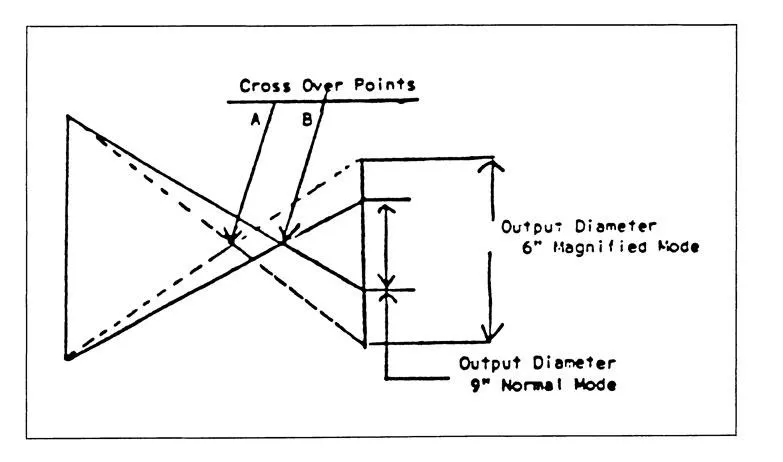
In the 9-in. mode, the electrostatic focusing voltage is decreased. The electrons focus to a point, or cross, close to the output phosphor, and the image is actually smaller than the phosphor. In the 6-in. mode, the electrostatic focusing voltage is increased, and the electrons focus farther away from the output phosphor. After the electrons cross, they diverge so the image on the output screen is larger than the 9-in. mode. The physical size of the input and output screens is the same in both modes; the only thing that changes is the size of the output image. Therefore, the 6- and 9-in. modes have different minification gains. Exposure factors are automatically increased when the unit is used in the magnified mode to compensate for the decreased brightness from minification. The ratio of patient exposure is calculated using this formula:
Example: When operating the image intensifier in the magnified 6-in. mode from the normal 9-in. mode, the patient will receive how many times more exposure?
Answer:
It is important to note that the normal mode is always used to view larger anatomic areas with less patient exposure. When size is unimportant, the magnified mode is used for better resultant image quality. The mA is automatically increased when the unit is used in the 6-in. magnified mode to compensate for the decreased brightness. Therefore, patient dose is increased.
Conversion Factor and Gain
When x-ray image intensifier tubes were first introduced, some means was needed to express their increased intensity. Because of the past familiarity with conventional fluoroscopic screens, it became commonplace to compare the image intensifier tube to the screen. The brightness gain, or “intensification gain” as it was called, was then expressed as the luminance of the output screen compared to the luminance of a standard Patterson fluoroscopic screen with the same incident radiation. The brightness gain is the ratio of the two illuminations:
The first image tubes that gained widespread acceptance had gains on the order of 3,000 or possibly a little higher. As improvements in design and manufacturing came along, this gain grad...
Table of contents
- Cover
- Half Title
- Title Page
- Copyright Page
- Dedication
- Table of Contents
- Preface
- Author
- Chapter 1: Image Intensifier System
- Chapter 2: Objective and Camera Lenses
- Chapter 3: Closed Circuit Television Systems
- Chapter 4: Recording the Television Image
- Chapter 5: Computerized Fluoroscopic Image Intensification
- Chapter 6: Fluoroscopic Image Production
- Chapter 7: Factors Affecting Patient and Operator Exposure
- Chapter 8: Health Effects of Low Level x-ray Exposure
- Chapter 9: Biological Effects and Significance of x-ray Exposure
- Chapter 10: Personnel Radiation Protection
- Chapter 11: Personnel Monitoring
- Chapter 12: Pediatric Fluoroscopy
- Chapter 13: Mobile Image Intensification Equipment
- Chapter 14: California Radiation Control Regulations— Responsibility of the Supervisor and Operator
- Chapter 15: Three-Dimensional Fluorographic Anatomy
- Chapter 16: Fluoroscopy Quality Assurance and Quality Control Program
- Appendix A: Answers to Review Questions
- Appendix B: Statement of Competency
- Appendix C: Review Test/Answers
- Appendix D: Laboratory Experiments
- Appendix E: Glossary
- Appendix F: Bibliography
- Index
Frequently asked questions
Yes, you can cancel anytime from the Subscription tab in your account settings on the Perlego website. Your subscription will stay active until the end of your current billing period. Learn how to cancel your subscription
No, books cannot be downloaded as external files, such as PDFs, for use outside of Perlego. However, you can download books within the Perlego app for offline reading on mobile or tablet. Learn how to download books offline
Perlego offers two plans: Essential and Complete
- Essential is ideal for learners and professionals who enjoy exploring a wide range of subjects. Access the Essential Library with 800,000+ trusted titles and best-sellers across business, personal growth, and the humanities. Includes unlimited reading time and Standard Read Aloud voice.
- Complete: Perfect for advanced learners and researchers needing full, unrestricted access. Unlock 1.4M+ books across hundreds of subjects, including academic and specialized titles. The Complete Plan also includes advanced features like Premium Read Aloud and Research Assistant.
We are an online textbook subscription service, where you can get access to an entire online library for less than the price of a single book per month. With over 1 million books across 990+ topics, we’ve got you covered! Learn about our mission
Look out for the read-aloud symbol on your next book to see if you can listen to it. The read-aloud tool reads text aloud for you, highlighting the text as it is being read. You can pause it, speed it up and slow it down. Learn more about Read Aloud
Yes! You can use the Perlego app on both iOS and Android devices to read anytime, anywhere — even offline. Perfect for commutes or when you’re on the go.
Please note we cannot support devices running on iOS 13 and Android 7 or earlier. Learn more about using the app
Please note we cannot support devices running on iOS 13 and Android 7 or earlier. Learn more about using the app
Yes, you can access Principles of Fluoroscopic Image Intensification and Television Systems by Robert J. Parelli in PDF and/or ePUB format, as well as other popular books in Law & Forensic Science. We have over one million books available in our catalogue for you to explore.