Now in its third edition, Electricity for the Entertainment Electrician & Technician is a comprehensive, practical study guide for aspiring and working professionals in live event production.
The book covers every aspect of power distribution from the fundamentals, like basic circuits, to 3-phase power, power calculations, grounding and bonding, electrical safety, portable power generators, and battery power. With ample photographs and illustrations, practice problems and solutions, and real-world examples from experience and first-hand accounts, it provides readers with the knowledge to safely design, set up, and monitor power distribution systems. The third edition expands on grounding and bonding, portable power generators, balanced and unbalanced 3-phase power calculations, battery power, and more. The last chapter walks readers through the process of prepping for a show, setting up a portable power distribution system, and monitoring every aspect of the system, including voltage, current, and heat using an infrared camera, explaining in detail best practices and the logic behind them.
Covering topics that are listed in the content outline for the ETCP Entertainment Electrician Certification exam as well as the ETCP Portable Power Distribution Technician Certification exam, this reference supports practicing technicians and provides new technicians the assistance they need for a successful career in the entertainment industry.
Additional resources, including conversion tables, voltage spreadsheets, articles from Lighting & Sound International, Lighting & Sound America, and Protocol, and animations and illustrations depicting electricity and electric power distribution developed for the author's workshops, can be found on the companion website www.electrics.tech.
Trusted by 375,005 students
Access to over 1.5 million titles for a fair monthly price.
Electricity is a fascinating phenomenon. It is energy that can be manifest as light, sound, heat, or movement, and that's why it is so important to those of us in the entertainment industry. We use it to create fantastic lighting, beautiful sound, awesome video images, and spectacular special effects. But to a novice, the behavior of electricity can be elusive and challenging to understand because we can't see it; its nature is obscured by a veil of mystery.
Imagine how our perception of water might change if we could not see it. People would appear to magically fly through the air when they were swimming, and ocean waves would appear to be unexplainable forces that could knock you over at seemingly random times as you walked along the beach.
That's how I felt about electricity from a very early age. I was about 10 years old when I became fascinated with electronics and mystified by how radios and televisions work. I struggled to understand how a person's voice could come out of a radio or how a moving image could appear on a television. I decided I was going to find out.
One day my parents left me alone at the house, which was usually an invitation to trouble. It was then that I decided I was going to discover the secrets of electronics, so I took one of my father's old radios out to the garage. I was sure that if I could just have a peek inside, I could figure out how it worked. So, I took a screwdriver and removed the four screws that secured the cover of the radio to the chassis.
I know what you're thinking, but I didn't get shocked nor did I cause a short circuit and a shower of sparks. By that time, I knew enough to unplug the radio before I took it apart. But instead of uncovering the mysteries of electronics, what I found was a circuit board with transistors, resistors, capacitors, a transformer, and a speaker. That did nothing to help pull back the veil of mystery.
But I wasn't going to let that stop me. I just knew that if I could look inside of one of those components that I could figure it out. After all, I was a smart 10-year-old kid. So, I took a pair of pliers and randomly selected a component on the circuit board. It turned out to be a resistor. I wiggled it back and forth until it broke free from the circuit board, and then I took what I soon learned was one of my favorite tools for analyzing electronic devices—it's called a hammer—and I smashed the resistor in order to get a good look inside. All I found was a pile of black carbon powder. Again, that did nothing to help me figure it out. My desire to learn how it worked only intensified.
Years later when I went to high school and I found out they were offering an electronics class, I jumped at the opportunity. I would finally learn how these devices worked.
This was a two-year class, and in my first year there was a mix of first-year and second-year students. From day one, the teacher started talking about voltages and currents, and for the first couple of weeks, I was completely and hopelessly lost—until he explained it in terms I could understand. He told us how electricity behaves like water.
Electricity Behaves Like Water
A hydraulic system, he said, has some similarities to an electrical system. Think of a big municipal water tower. The tank holds water high in the air, and the force of gravity pushes down on the surface of the water, which produces water pressure around the walls of the tank. If there is an open pipe attached to the water tower, water will flow through it, and the amount of water that flows depends on the amount of water pressure; the greater the water pressure, the more water will flow through the pipes. The only other limiting factor is the size of the pipes; the bigger the cross-sectional diameter of the pipe, the more water that can flow through it.
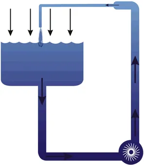
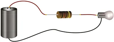
Water pressure in a hydraulic system is much like the “electrical pressure” or voltage in an electrical system. The pipe that carries the water to your neighborhood is like a conductor that carries electrical current from an electrical supply to a lamp or other load. The resistance to the flow of water due to the size of the pipe is like the resistance to the flow of electricity in an electrical circuit. The bigger the pipe, the easier the water flows; the smaller the pipe, the less the amount of water that can get through the pipe. A small pipe, then, is like a conductor with a smaller cross-sectional diameter, and a large pipe is like a large conductor. Along the way there might be valves that turn the water on or off, much like the electrical switches that turn electrical current on or off; when the tap is on, the water flows, and when the light switch is on, the current flows. (See Figures 1.1a and 1.1b.)
FIGURE 1.1A Gravity pushes down on the surface of the water in the tank, which produces the water pressure that forces water through the pipe. The water pump (bottom right) increases the water pressure so that it can rise higher than the level in the tank. The smaller pipe resists the flow of water that runs through the pipe and reduces the flow of water.
FIGURE 1.1B The electrical parallel to a hydraulic system is a DC circuit; the electrical pressure (voltage), supplied by a battery drives electrical current through the conductors (wires) in much the same way that the water pressure forces the water through the pipes. The resistor in the circuit limits the flow of electricity through the lamp so that the lamp will not blow or burn up.
Voltage, Current, and Resistance
A production electrician friend of mine once told me that I speak “engineer.” “What do you mean by that?” I asked.
“Well,” he said, “most production electricians and technicians say ‘volts,’ ‘amps,’ and ‘ohms,’ but you say ‘voltage,’ ‘current,’ and ‘resistance.’”
“True,” I said. “But we're referring to the same thing!”
“Yeah,” he said, “but not everyone knows that.”
He is right. Production electricians and technicians often carry meters that they use to measure voltage, current, and resistance, but that's not how the labels read. The labels read “volts,” “amps,” and “ohms.” Many of us learn on the job and never have the opportunity to have formal training in electricity or electronics, so are never taught the difference between voltage and volts, current and amps, resistance and ohms. And sometimes when we encounter these terms, it can be confusing.
The difference is that volts, amps, and ohms are the units of measure of voltage, current, and resistance, respectively. It is no different than referring to kilometers, kilograms, and Kelvins instead of distance, weight, and temperature.
Terminology is important because confusion in communicating can lead to problems. Suppose, for example, a show has a 150-amp power distribution system (or “power distro”) and the head electrician says to a tech, “What's the current on the neutral?” What might happen if the tech misunderstands and interprets it as, “What is currently the voltage on the neutral?” If he takes a voltage reading instead of a current reading, and calls out “120,” then it would seem as if everything was okay. But if the current flowing through the 150-amp conductor was actually 175 amps, that's a problem! Miscommunication can cause problems or makes them worse.
Communicating clearly and effectively is very important, and that includes concepts and terminology. If we use different terminology, we might as well be speaking different languages. It is better, therefore, to learn the terminology of the craft we so love.
Resistance
Resistance is the opposition to the free flow of electrical current. It is a physical phenomenon caused by free-flowing electrons, which are subatomic charged particles. Electricity is the flow of these particles, and as they make their way through a conductor, they collide with each other, producing friction and heat. If two different conductors with different resistances are carrying the same amount of current, the conductor with the highest resistance will also have a higher temperature. If two conductors with the same amount of resistance are carrying different amounts of current, the one with the highest current will have a higher temperature.
Every electrical circuit has to have at least some resistance; otherwise, too much current would flow, and the components would overheat and melt. Resistance is sometimes desirable and sometimes undesirable. It is desirable when we want to limit flow of current through a circuit to prevent it from overloading. It is undesirable when it comes to energy efficiency because the energy that is converted from electrical to heat energy is dissipated into the atmosphere and lost.
In some cases, we take advantage of the electrical-to-heat energy conversion process. Some circuit breakers have a mechanism that converts electrical current to heat. If too much current flows, it gets hot enough to trip the mechanism and interrupt the circuit, thereby preventing too much current from flowing. Incandescent lamps convert electrical current to heat, which causes the filament to produce light. Without this conversion process, neither thermal circuit breakers nor incandescent lamps would work. In other cases, we try to maximize energy efficiency by minimizing lost heat, such as in conductors and other circuit elements.
Electric circuits are designed to have the right amount of resistance to control the flow of current and limit it to the right intensity. An incandescent lamp, for example, has a tungsten filament with a very specific resistance to control the intensity of the current and thus, the wattage of the lamp. The resistance of the filament is determined by the thickness and length of the tungsten wire.
A perfect conductor is one that has no resistance. In the real world, under normal circumstances, no such thing exists. Even large feeder cable has a small amount of resistance. Some materials—like copper, aluminum, and gold—are very good conductors, and some—like rubber, glass, and air—are very poor conductors under normal circumstances. The resistance of any material depends on its atomic structure. If a material has high enough resistance, it can be used as an insulator to protect against electric shock. For example, some cables have a jacket made of thermoset, which is a polymer or plastic, and that makes it safer to handle because the jacket provides shock protection.
The unit of measure of electrical resistance is called the ohm, after German physicist Georg Ohm (1789–1854). Resistance is abbreviated by the letter “R,” but its unit measure is abbreviated by the Greek symbol omega (Ω). An ohm meter or a multimeter with a resistance function, for example, typically uses the omega symbol to indicate the resistance setting.
Resistance is an integral part of electric circuits, yet production electricians and technicians rarely, if ever, measure it. More often they measure the voltage applied to a system or component of a system and the current flowing through the system or a branch of the system. But they are all related, and in order to understand how circuits work, it is critical to understand the relationship between voltage, current, resistance, and power. The relationship between voltage, current, and resistance is established by a formula that we refer to as “Ohm's law,” after the aforementioned George Ohm, a German physicist who explored the relationship. The relationship between voltage, current, and power is established by the power formulas. We'll discuss these in detail in later chapters.
Production electricians and technicians often use an ohm meter or a multimeter with an ohm meter function, but usually not to read the value of resistance. Instead, it is often used as a continuity tester. Very low resistance between two points in a circuit means there is continuity or there is a continuous conductive path between the two leads of the tester. (In theory, continuity is 0 Ω, although in the real world ...
Table of contents
Cover Page
Half-Title Page
Title Page
Copyright Page
Dedication Page
Contents
Preface
Acknowledgements
CHAPTER 1 Foundations of Electrical Systems
CHAPTER 2 Circuits and Circuit Laws
CHAPTER 3 DC Power
CHAPTER 4 Introduction to Alternating Currents
CHAPTER 5 3-Phase Power
CHAPTER 6 Resistive, Capacitive, and Inductive Loads
CHAPTER 7 3-Phase Power Calculations
CHAPTER 8 Portable Power Generators
CHAPTER 9 Battery Power
CHAPTER 10 Electrical Safety
CHAPTER 11 Grounding/Earthing and Bonding
CHAPTER 12 Overcurrent Protection
CHAPTER 13 Dimming Systems
CHAPTER 14 Portable Power Distribution
CHAPTER 15 Show Prep, Setup, and Monitoring
Appendix 1: The Physics of Electricity
Appendix 2: The History of Alternating Current System
Appendix 3: A (Very) Short History of Portable Power Distribution
Appendix 4: International Systems of Units (Si), Prefixes, and Scientific Notation
Appendix 5: Worldwide Voltages and Frequencies
Appendix 6: Unbalanced 3-Phase Loads Calculations
Appendix 7: IP Ratings and NEMA Ratings
Appendix 8: Useful Formulas
Appendix 9: Answers to Practice Problems
References
Index
Frequently asked questions
Yes, you can cancel anytime from the Subscription tab in your account settings on the Perlego website. Your subscription will stay active until the end of your current billing period. Learn how to cancel your subscription
No, books cannot be downloaded as external files, such as PDFs, for use outside of Perlego. However, you can download books within the Perlego app for offline reading on mobile or tablet. Learn how to download books offline
Perlego offers two plans: Essential and Complete
Essential is ideal for learners and professionals who enjoy exploring a wide range of subjects. Access the Essential Library with 800,000+ trusted titles and best-sellers across business, personal growth, and the humanities. Includes unlimited reading time and Standard Read Aloud voice.
Complete: Perfect for advanced learners and researchers needing full, unrestricted access. Unlock 1.5M+ books across hundreds of subjects, including academic and specialized titles. The Complete Plan also includes advanced features like Premium Read Aloud and Research Assistant.
Both plans are available with monthly, semester, or annual billing cycles.
We are an online textbook subscription service, where you can get access to an entire online library for less than the price of a single book per month. With over 1.5 million books across 990+ topics, we’ve got you covered! Learn about our mission
Look out for the read-aloud symbol on your next book to see if you can listen to it. The read-aloud tool reads text aloud for you, highlighting the text as it is being read. You can pause it, speed it up and slow it down. Learn more about Read Aloud
Yes! You can use the Perlego app on both iOS and Android devices to read anytime, anywhere — even offline. Perfect for commutes or when you’re on the go. Please note we cannot support devices running on iOS 13 and Android 7 or earlier. Learn more about using the app
Yes, you can access Electricity for the Entertainment Electrician & Technician by Richard Cadena in PDF and/or ePUB format, as well as other popular books in Media & Performing Arts & Theatre. We have over 1.5 million books available in our catalogue for you to explore.