From the leading magazine for metalworkers since 1898, Model Engineer, comes this curated collection of practical advice and useful tips anyone in the industry needs to know! Jam-packed with information that's as relevant today as it was during its original publication, spanning from the 1890s to the 1960s, Metalworkers' Hint and Tips include sections on lathes and lathe work, benchwork, machine tools and accessories, electrical queries, and other miscellaneous topics. These best-of tips are the most fascinating, helpful, and time- and money-saving tips metalworkers will ever need! Author Vic Smeed was the editor of Model Maker magazine for almost 20 years and is the author of 16 modeling, metalworking, and other workshop books.

- 250 pages
- English
- ePUB (mobile friendly)
- Available on iOS & Android
eBook - ePub
About this book
Trusted by 375,005 students
Access to over 1.5 million titles for a fair monthly price.
Study more efficiently using our study tools.
Information
SECTION 1
Lathes and Lathework
Removable Nose for a Mandrel
H.S. Wheeler (November 1964)
A useful addition to a Myford ML7 lathe is a removable nose for the outer end of the mandrel. I found it quite simple to make.
It consists of a nosepiece which is a replica of the standard mandrel nose, and an extending neck which is stepped.
The ¾ in. dia. step passes through the hole in the gear guard and forms a stop at the end of the mandrel. The end of the smaller 19/32 in. dia. step is sawcut and coned out, and a mating cone is made.
A 5/16 in. dia. clearing hole is drilled right through the attachment and in this is passed a long stud, screwed 5/16 in. Whitworth at each end.
To assemble the device on the lathe we need only push it right home in the mandrel and then tighten the external nut, which draws the cone into the taper and expands the end of the stepped part. The clamping is quite rigid.
If the standard faceplate is now screwed on the nose part, it will be very useful for turning the mandrel by hand, as in small screwing or tapping operations. By securing the appropriate disk to the faceplate you can also use the device for sanding or finishing, by running the lathe at top speed. The mandrel should then be run in reverse, to prevent the possibility that the faceplate will unscrew.
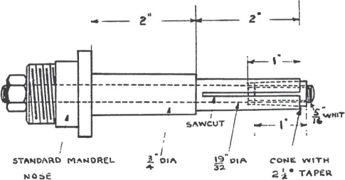
It will save you the removal of a good deal of stock if you make the nosepiece and stepped tailpiece separately and then screw and pin the tailpiece into the nosepiece. You can remove the device instantly by slackening off the external nut and giving the spindle a light tap to clear the tapered cone, when the whole can be pulled out.
Center with Tool-setting Peg
(January 1924)
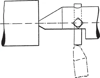
The appended view represents an idea for tool-setting down to quite small diameters by the use of a peg inserted in a cross-hole in a special back-center. The latter should be cut away as shown so that the tool may pass along when the peg is set only to a small amount of projection.
Divider for a Portass
A.G. Allnut (April 1964)
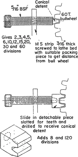
Readers with a Portass or similar lathe may be interested in my divider, if they have a 60t bull wheel. The conical shape detent is, perhaps, not perfect but it works well enough.
Tapers
‘Geometer’ (January 1957)
The desirable true running of a pulley or flywheel taper-fitted on a shaft is generally best ensured by finishing faces and outside diameter with the component mounted on a mandrel running between centers in the lathe. All important surfaces are thus finished at one setting and the wheel is both parallel and concentric—a condition difficult to achieve by chucking and re-chucking no matter how carefully this may be done.
The preliminary roughing out is advisedly done in a chuck (which can be a four-jaw independent type with the jaws reversed if necessary, since heavier cuts can be taken in a chuck than on a mandrel) leaving about 1/64 in. surplus for finishing. In this way, scale or any hard spots in the casting can be successfully dealt with in the rough machining, using a slow rotational speed and taking cuts deep enough to be everywhere well below the surface.
Diagrams A and B illustrate typical chuck set-ups for rough machining a small flywheel, the material removed at each being shown by the shaded areas. At each set-up the wheel is pushed back to the jaws for facial alignment, and the jaws are regulated for peripheral or general spinning truth.
Although it is not vital to do so, it is generally best to machine the taper bore on the first set-up, and also to turn along the outside diameter as far as possible. On the second set-up it is then practicable to fit a taper mandrel in the bore and employ its end for checking and truing— if it should happen that it is difficult to apply the pointer of a surface gauge to a portion of the outside diameter.
Moreover, should a small error result from the setting, cleaning cuts can easily be taken on the mandrel set-up C since the particular faces will be toward the tailstock.
Taper uniformity
When the shaft is available on which the wheel is to fit, it can be tried in the taper as this is machined (or reamed) in order to locate the wheel endwise correctly— in which respect, should the taper bore be made slightly too large a reducing cut can always be taken over the face.
Alternatively, the bore can be sized from a reamer or mandrel, as at D, which may be necessary if the component is a replacement, or one is requiring to stan-dardize tapers for wheels to be fitted on different shafts. In the case of a mandrel, a shoulder can be left in machining or a sleeve can be fitted for a distance X to obtain when the taper is at correct size; in the case of a reamer, a sleeve is essential when the distance can be measured with a rule, or a small gauge made just to push into the space.
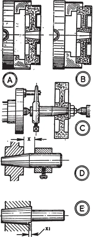
A common type of gauge for this method of sizing tapers is as E, where the taper portion ends in a step on one side X1. On the tool being pushed tightly into the bore to be tested, the step should go just below the surface while the full diameter just stands proud—showing the bore to be within its particular tolerance.
Should the gauge enter too far a light correcting cut can always be taken across the face—assuming there remains sufficient material on other faces to machine them into relationship—which is as good a reason as any for finishing the taper early in the proceedings.
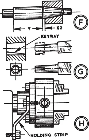
The principle also applies to a shaft F where a ring gauge (corresponding to the component) is used. This may have a step X2 to locate the position where the taper finishes at the full diameter, or at the opposite end on the small diameter, though a better way is to take the distance Y from the face to a shoulder or the end of the shaft.
If a keyway is required in a wheel its cutting should be the final operation. From square drill rod a tool is made as G, turning the shank, filing the surplus to tool shape, then hardening and tempering. Planing cuts are taken from the saddle with the chuck secured against rotation, as at H, by a holding strip from backplate to headstock.
Cutting Metric Threads
The use of a 127-toothed wheel for metric screwcutting on an English lathe By Geo. Gentry (July 1955)
This article relates to a problem which is constantly recurring in both amateur and professional workshops, and it is proposed to deal with it in some detail to satisfy the requirements of querists who have asked for advice on how to produce metric threads on lathes with fractional-inch pitch lead screws. In the particular instances, the pitch of the lead screw is not specified, but it will be assumed that it is 8 t.p.i., as this is the pitch most commonly employed on English lathes of the sizes employed by model engineers. Neither is it known what change wheels may be available, but if the basic principles of the calculations are grasped, they can be adapted to different lead screws or change wheels by the use of elementary arithmetic.
Ratio of wheel numbers
If the pitch of a screw to be cut is given, the ratio of gearing required is expressed as the ratio of the pitch to be cut (on the mandrel end) to the pitch of the lead-screw (on its appropriate end). If, however, the reciprocal of the pitch be given (i.e. number of threads per inch), the reciprocal of the lead screw pitch is put on the mandrel, and the screw to be cut on the leadscrew. In the first case, as an example, if it is desired to cut a pitch of 1 mm. with a leadscrew of 2 ½ mm., the ratio of gears will be ½ ½ or 1 to 2 ½ mandrel to screw.
In the second case, if it is desired to cut 12 t.p.i. with a lead screw of 8 t.p.i., the ratio of gears will be 8/12 or 8 to 12 mandrel to screw.
Applying the second case, to explain the use of the 127 wheel, it is necessary to know that there are 25.4 mm. in 1 in., or a 1 mm. pitch screw may be expressed as 25.4 t.p.i. This is not exactly correct but has only an error of the order of two millionths of an inch in an inch which is negligible entirely.
If then we require to cut 25.4 t.p.i. with a leadscrew of 8 t.p.i., applying the second case, the ratio of gears will be 8/25.4 or 8 to 25.4 mandrel to screw. Thus:
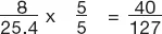
the smallest factor which can be used to bring 25.4 to whole numbers being 5. Thus a simple train (i.e. not a compound train) made with a 40 wheel on mandrel end and 127 wheel on the 8 t.p.i. lead-screw end will cut 25.4 t.p.i. or 1 mm. pitch (Fig. 1). Forty is the driver and 127 the driven or follower of the train.
Keeping to simple trains throughout and retaining the 127 on the screw, the 40 wheel must be replaced with wheels corresponding to the fractions of mm. pitch or multipliers of mm. pitch required. Thus to cut ½ mm. pitch, ½ of 40 or 20 will be required on mandrel as a driver. To cut 0.6mm. pitch 0.6 of 40 = 24 wheel will be required and to cut 0.7 mm. 0.7 of 40 = 28 wheel will be required and none others, if simple trains are required. This explains the following table, a study of which will explain that to cut fractions of mm. we speed down the screw and to cut over 1 mm. speed up the same. The use of idle wheels is given at the end of this article.
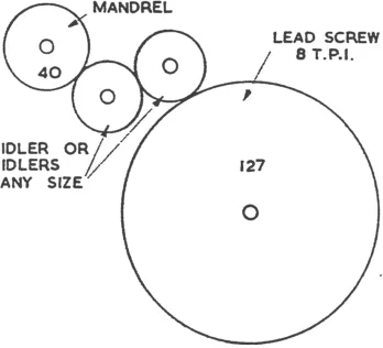
Fig. 1
Compound trains
To make clear the principle of compounding, which will be necessary in some cases where the drivers given are not available, the interested reader must understand the idea of speeding down or up in proportion to the fraction or multiplier of 1 mm. required to be cut. If, for instance, ½ mm. is required and no 20 wheel is available, the compounding wheels must have the ratio 2 to 1 down, say 48 and 24, thus retaining the original 40 driver, put it 40 driving into 48 on intermediate stud and 24 keyed to 48 on same (and running with it) driving the 127 on screw (Fig. 2).
If there should be trouble in getting the wheels to come together, the 24 and 40 drivers may be changed about, giving 24 on mandrel driving 48 on stud, and 40 on stud (keyed to 48) driving 127 on screw. If, however, 24 and 48 are either or both not available:
56 and 28; 60 and 30; 64 and 32 or any 2 to 1 wheels available may be used in the same way. Applying the principle where 0.6 mm. is required and no 24 is available, the compounding wheels must have the ratio 1 to 0.6 down or 10 to 6, say wheels 50 to 30 giving 40 ...
Table of contents
- Cover
- Title
- Copyrights
- Contents
- Introduction
- Section 1 Lathes and Lathework
- Section 2 Benchwork
- Section 3 Machine Tools and Accessories
- Section 4 Electrical
- Section 5 Miscellaneous
Frequently asked questions
Yes, you can cancel anytime from the Subscription tab in your account settings on the Perlego website. Your subscription will stay active until the end of your current billing period. Learn how to cancel your subscription
No, books cannot be downloaded as external files, such as PDFs, for use outside of Perlego. However, you can download books within the Perlego app for offline reading on mobile or tablet. Learn how to download books offline
Perlego offers two plans: Essential and Complete
- Essential is ideal for learners and professionals who enjoy exploring a wide range of subjects. Access the Essential Library with 800,000+ trusted titles and best-sellers across business, personal growth, and the humanities. Includes unlimited reading time and Standard Read Aloud voice.
- Complete: Perfect for advanced learners and researchers needing full, unrestricted access. Unlock 1.5M+ books across hundreds of subjects, including academic and specialized titles. The Complete Plan also includes advanced features like Premium Read Aloud and Research Assistant.
We are an online textbook subscription service, where you can get access to an entire online library for less than the price of a single book per month. With over 1.5 million books across 990+ topics, we’ve got you covered! Learn about our mission
Look out for the read-aloud symbol on your next book to see if you can listen to it. The read-aloud tool reads text aloud for you, highlighting the text as it is being read. You can pause it, speed it up and slow it down. Learn more about Read Aloud
Yes! You can use the Perlego app on both iOS and Android devices to read anytime, anywhere — even offline. Perfect for commutes or when you’re on the go.
Please note we cannot support devices running on iOS 13 and Android 7 or earlier. Learn more about using the app
Please note we cannot support devices running on iOS 13 and Android 7 or earlier. Learn more about using the app
Yes, you can access Metalworkers' Hints and Tips for Home Machinists by Vic Smeed, Vic Smeed,Vic Smeed in PDF and/or ePUB format, as well as other popular books in Technology & Engineering & Mining Engineering. We have over 1.5 million books available in our catalogue for you to explore.