The book describes the methods and procedures to optimally applying lubricant to all kinds of general purpose machines. These include process pumps, electric motors and other equipment incorporating rolling element bearing where traditional methods are usually very much out of step with best available practices. Failure analysis, reliability strategies, remedial steps or desirable substitute approaches are also explained.
eBook - ePub
Optimized Equipment Lubrication
Conventional Lube, Oil Mist Technology and Full Standby Protection
- 255 pages
- English
- ePUB (mobile friendly)
- Available on iOS & Android
eBook - ePub
Optimized Equipment Lubrication
Conventional Lube, Oil Mist Technology and Full Standby Protection
About this book
Trusted by 375,005 students
Access to over 1.5 million titles for a fair monthly price.
Study more efficiently using our study tools.
Information
Part C: Full equipment standstill/standby protection
Chapter 8 Outdoor equipment storage and preservation yards
8.1 Management digest
The core setup for an equipment storage or protection yard is shown in Fig. 8.1. As many as eight, nominally quarter-inch-size tubing connections are provided on each of the 20–30 manifolds threaded into the common header. The 2″ header is slightly sloped (assume typically 0.5° to perhaps 1° off true horizontal), with the lower end of the header near the midsize OMG, in this case a small oil mist generator/oil reservoir combination unit. One of many manifolds is shown circled. This OMG can later be permanently installed in one of the facility’s process units.

Fig. 8.1: Core setup of an outdoor storage yard consisting of an oil mist generator module, 42-gallon drum of oil, header, and multiple manifolds (source: Don Ehlert).
8.2 Overview and principles of storage yards
This chapter brings to the reader’s attention that equipment staged in outdoor storage yards is serviced by the same oil mist generators (OMGs) that are used in permanent oil mist consoles or cabinets. The reclassifiers secured in equipment bearing housings are the same ones used once the equipment is installed in its permanent location. However, the owner-operator can request and specify that the outside storage OMG will later become a warehouse spare and that the very same warehouse spare OMG can be set up as an emergency module next to a machine that suffers from frequent bearing failures. Initially though, outdoor storage yards capitalize on the merits of oil mist as a preservation medium. We wish to point out that Appendix III also addresses the general topic. Appendix III is based on API RP-686, whereas Chapter 8 deals entirely with the author’s decade-long experience.
8.3 Modifying new equipment upon arrival at a storage yard
Some minor sizing and configurational differences may exist between small and large storage facilities. Outdoor storage yards have been used throughout the world, and only a single US location ever used wooden rain and sun shelters for storage. The author strongly believes that storage shed decisions were made by lower level supervisors who, upon ultimate dismantling, transported the wooden beams and plywood panels to their small farms and weekend homes for re-use. However, an estimated 99% of temporary outdoor storage facilities were erected without such protective woodwork because such shelters are simply not needed.
As a general rule, equipment arriving in a storage yard for oil mist preservation receives the same preparatory treatment as equipment being readied for conventional, liquid oil-based preservation. Noteworthy facts are as follows:
- Oil mist will coalesce when the equipment operates. Operation causes a measure of turbulence, whereby the atomized particles get knocked together and become large and heavy. Turbulence is obviously not created in equipment that is standing still. Without turbulence, the reclassifying (conversion) of oil mist to liquid oil proceeds at a rather slow rate in non-running equipment.
- A low point drain location is being identified and left open at all times. This low point is useful because it prevents oil accumulation and ensures throughflow of a small amount of mist. The mist lost through a drain orifice equals the makeup mist.
- With rare exceptions, a 1 mm minimum, 3 mm maximum drain orifice is all that is needed.
- A machine in storage and ready for preservation can be slanted or skewed to create or locate a convenient and/or accessible low point drain. A flat pan can be used to catch this drainage for monitoring and proper disposal.
- A rotor blanketed by oil mist should be manually rotated two and a half turns every 6 months. This ensures a light coating of oil remains established throughout a rolling element bearing and avoids false brineling (indentation) at or near the 6 o’clock load points.
Only steam turbines require special cleanup before recommissioning. Accordingly, the following precautions apply only to steam turbines:
- Use oils with formulations that will not promote future stress corrosion cracking.
- Prior to machine commissioning, blow steam through the equipment. This removes the thin coating of oil that would have accumulated on the surfaces.
- Collect some of the exiting blow-down steam and observe if it contains oil.
If monitoring the discharge from a low-point drain is deemed too pedestrian, reasonably accurate calculation of residual oil films on machine interiors is feasible. As a not so general rule, one could proceed with an academic calculation. One could calculate the total interior surface areas that are being wetted in a machine and then assume that a 0.0005″ thick oil film will coat these surfaces. Knowing the area and oil film thickness, one could calculate the total volume of oil that will exist in the equipment in a time period and convert this to milliliters of oil, knowing that 3.85 L equates to a gallon. A liter equals 1,000 mL. Assume the premium preservative oil (Product A) costs $18 per gallon and figure out what it all costs after subtracting oil lost. One would have to account for oil lost through the 3 mm orifice, based on an equipment internal pressure of 0.1 to perhaps 0.3 psi above ambient and recalling that the oil-to-air ratio is 1:200,000.
A downward sloping plastic line (3–6 mm tubing diameter) is connected to each bearing housing and a drain plug (with a normally 1 mm and maximally 3 mm drilled hole) is installed at the bottom of the bearing housing. If the equipment arrives in crates as shown in Fig. 8.2, the crate must initially be opened and then reclosed after oil mist preservation commences.

Fig. 8.2: In this storage and preservation yard, crated machinery is initially accessed by removing one of the four sides of the crate (source: Don Ehlert).
However, opening the shipping crate can probably be avoided by specifying, and getting the manufacturer to provide, the external connecting panels seen in Fig. 8.3. Note, also, the care with which the pump inlet and outlet nozzles have been covered by this manufacturer. The crates illustrated in Figs. 8.2 and 8.3 are quite obviously ready for the oil mist tubing seen in many of the various illustrations that follow.
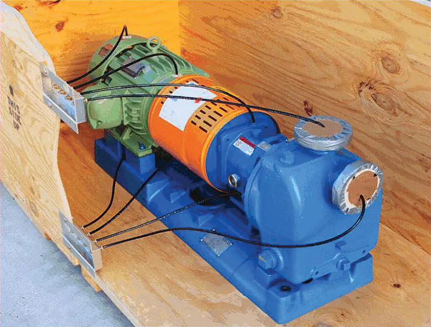
Fig. 8.3: Cutaway image of a self-priming pump and electric motor driver, where all tubing connections are led to the two external panels (source: Don Ehlert).
In case machinery arrives unprepared for outdoor storage, an EPC/owner’s SME team will have seen to it that a small OMG/oil supply combination is standing by to protect the machines, Fig. 8.4. A proactive EPC/SME team will have ascertained that the principal OMG components can later become spares for permanently installed new or pre-owned oil mist modules. Components shown in Fig. 8.4 are ideal emergency lubrication modules for the occasional pumps that are the victims of lube design application errors.
Both Figs. 8.2 and 8.5 depict crated equipment that was purchased overseas and arrived after crossing an ocean. The captions provide additional information. Note the downward sloping tubing in Fig. 8.5; it prevents the formation of low pockets where coalesced oil could accumulate and impede proper oil mist flow. We recall that 2.31 ft = about 28″ of water column (~32″ of oil column) equals 1 psi. If the oil mist pressure inside a protected machine or vessel is 0.1 psi, a U-shaped 2.8- or 3.2″ tall low point/pocket in the tubing may act as a plug, and no oil mist will reach the intended destination.

Fig. 8.4: Outdoor storage setup with oil mist elements that can later be used as part of a permanent in-plant oil mist console (source: T. F. Hudgins, Houston, TX).
The oil mist application details shown in most of our images were originally specified by the user-purchaser. When the equipment arrived at its destination, the storage yard prepa...
Table of contents
- Title Page
- Copyright
- Contents
- Preface
- Introduction
- Part A: Bearings and optimally applying lubricant Examining rolling element bearings and traditional lubrication
- Part B: Fundamentals of oil mist technology How equipment outdoor preservation later becomes full standby protection
- Part C: Full equipment standstill/standby protection
- Index
Frequently asked questions
Yes, you can cancel anytime from the Subscription tab in your account settings on the Perlego website. Your subscription will stay active until the end of your current billing period. Learn how to cancel your subscription
No, books cannot be downloaded as external files, such as PDFs, for use outside of Perlego. However, you can download books within the Perlego app for offline reading on mobile or tablet. Learn how to download books offline
Perlego offers two plans: Essential and Complete
- Essential is ideal for learners and professionals who enjoy exploring a wide range of subjects. Access the Essential Library with 800,000+ trusted titles and best-sellers across business, personal growth, and the humanities. Includes unlimited reading time and Standard Read Aloud voice.
- Complete: Perfect for advanced learners and researchers needing full, unrestricted access. Unlock 1.5M+ books across hundreds of subjects, including academic and specialized titles. The Complete Plan also includes advanced features like Premium Read Aloud and Research Assistant.
We are an online textbook subscription service, where you can get access to an entire online library for less than the price of a single book per month. With over 1.5 million books across 990+ topics, we’ve got you covered! Learn about our mission
Look out for the read-aloud symbol on your next book to see if you can listen to it. The read-aloud tool reads text aloud for you, highlighting the text as it is being read. You can pause it, speed it up and slow it down. Learn more about Read Aloud
Yes! You can use the Perlego app on both iOS and Android devices to read anytime, anywhere — even offline. Perfect for commutes or when you’re on the go.
Please note we cannot support devices running on iOS 13 and Android 7 or earlier. Learn more about using the app
Please note we cannot support devices running on iOS 13 and Android 7 or earlier. Learn more about using the app
Yes, you can access Optimized Equipment Lubrication by Heinz Bloch in PDF and/or ePUB format, as well as other popular books in Physical Sciences & Chemistry. We have over 1.5 million books available in our catalogue for you to explore.