Control systems are pervasive in our lives. Our homes have environmental controls. Appliances we use at home such as the washing machine, microwave, etc. have embedded controllers. We fly in airplanes and drive automobiles, which make extensive use of control systems. The increase of automation in the past few decades has increased our reliance on control systems. A First Course in Control System Design discusses control systems design from a model-based perspective as applicable to single-input single-output systems. The emphasis in this book is on understanding and applying the techniques that enable the design of effective control systems. The book covers the time-domain and the frequency-domain design methods as well as the design of continuous-time and discrete-time systems.Technical topics discussed in the book include: - Modeling of physical systems - Analysis of transfer function and state variable models - Control system design via root locus - Control system design in the state-space - Control design of sampled-data systems - Compensator design via frequency response modification.
Trusted by 375,005 students
Access to over 1.5 million titles for a fair monthly price.
Obtain a physical system model from the component descriptions.
Obtain the system transfer function from its differential equation model.
Obtain a physical system model in state variable form.
Linearize a nonlinear system model.
Physical systems of interest to engineers include electrical, mechanical, electromechanical, thermal, and fluid systems, among others. The behavior of these systems is mathematically described by the dynamic equations, i.e., ordinary linear differential equations (ODEs), if lumped parameter assumption is made.
To model a system with interconnected components, individual component models can be assembled to formulate the system model. For electrical systems, these elements include resistors, capacitors, and inductors. For mechanical systems, these include inertias (masses), springs, and dampers (or friction elements). For thermal systems, these include thermal capacitance and thermal resistance. For fluid systems, these include the reservoir capacity and the flow resistance. All of these elements either store or dissipate energy, which gives rise to the time-varying or dynamic behavior of the systems.
Modeling of the physical system behavior involves two kinds of variables: flow variables that ‘flow’ through the components, and across variables that are measured across the components. For the electrical circuits, voltage or potential is measured across the circuit nodes, whereas current or electrical charge flows through the circuit branches. In mechanical linkage systems, displacement and velocity are measured across the connecting nodes, whereas force or effort ‘flows’ through the linkages. For thermal and fluid systems, heat and mass serve as the flow variables, and temperature and pressure constitute the across variables.
The relationship between flow and across variables defines the type of physical component being modeled. The elementary types are the resistive, the inductive, and the capacitive components. This terminology, taken from electrical circuits, also extends to other types of physical systems.
1.1 Physical Component Models
Let x(t) denote an across variable and q(t) denote a flow variable; then, the elementary component types are defined by their respective relationships, given as follows:
1. The resistive element:x(t) = k q(t).
For example, the voltage and current relationship through a resister is described by the Ohm’s law: V(t) = R i(t). Or, the force-velocity relationship though a linear damper is given as:
.
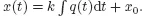
2. The capacitive element:
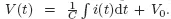
For example, the voltage and current relationship through a capacitor in electric circuit is given as:
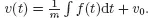
Similarly, the force-velocity relationship through an inertial mass element is given as:
3. The inductive element:
For example, the voltage-current relationship through an inductive coil in an electric circuit is given as:
Or, the force-velocity relationship though linear spring is given as:
1.1.1 First-Order Models
Electrical, mechanical, thermal, and fluid systems that contain a single energy storage element are described by first-order models. The order here refers to the order of the ODE used to describe the system. The mathematical model of each component is described in terms of the output variable, i.e., the variable that represents the output of the e...
Table of contents
Cover
Title Page
Copyright Page
Contents
Preface
Acknowledgement
List of Figures
List of Table
List of Abbreviations
1 Physical System Models
2 Analysis of Transfer Function Models
3 Analysis of State Variable Models
4 Control System Design Objectives
5 Cascade Controller Models
6 Control System Design with Root Locus
7 Sampled-Data Systems
8 Digital Controller Design
9 Control System Design in State-Space
10 Digital Controller Design in State-Space
11 Compensator Design via Frequency Response Modification
Appendix
References
Index
About the Author
Back Cover
Frequently asked questions
Yes, you can cancel anytime from the Subscription tab in your account settings on the Perlego website. Your subscription will stay active until the end of your current billing period. Learn how to cancel your subscription
No, books cannot be downloaded as external files, such as PDFs, for use outside of Perlego. However, you can download books within the Perlego app for offline reading on mobile or tablet. Learn how to download books offline
Perlego offers two plans: Essential and Complete
Essential is ideal for learners and professionals who enjoy exploring a wide range of subjects. Access the Essential Library with 800,000+ trusted titles and best-sellers across business, personal growth, and the humanities. Includes unlimited reading time and Standard Read Aloud voice.
Complete: Perfect for advanced learners and researchers needing full, unrestricted access. Unlock 1.5M+ books across hundreds of subjects, including academic and specialized titles. The Complete Plan also includes advanced features like Premium Read Aloud and Research Assistant.
Both plans are available with monthly, semester, or annual billing cycles.
We are an online textbook subscription service, where you can get access to an entire online library for less than the price of a single book per month. With over 1.5 million books across 990+ topics, we’ve got you covered! Learn about our mission
Look out for the read-aloud symbol on your next book to see if you can listen to it. The read-aloud tool reads text aloud for you, highlighting the text as it is being read. You can pause it, speed it up and slow it down. Learn more about Read Aloud
Yes! You can use the Perlego app on both iOS and Android devices to read anytime, anywhere — even offline. Perfect for commutes or when you’re on the go. Please note we cannot support devices running on iOS 13 and Android 7 or earlier. Learn more about using the app
Yes, you can access A First Course in Control System Design by Kamran Iqbal in PDF and/or ePUB format, as well as other popular books in Technology & Engineering & Civil Engineering. We have over 1.5 million books available in our catalogue for you to explore.