This textbook comprehensively presents different types of analog function circuits and outlines the function circuit types implemented with lowpass filters, peak detectors, and sample and hold circuits. The text analyzes the complete architecture of a function circuit, identifies the applications of op-amps for performing a function circuit, and explores new ways of deriving function circuits using a sawtooth wave generator and a triangular wave generator. It covers important topics including waveform generators, analog dividers, time division multipliers-cum-dividers (MCDs), peak responding MCDs, vector magnitude circuits, multifunction converters, and phase sensitive detector circuits. The textbook will serve as an ideal study material for senior undergraduate and graduate students in the fields of electrical, electronics, and communications engineering. The textbook is accompanied by teaching resources, including a solutions manual for instructors.
- 480 pages
- English
- ePUB (mobile friendly)
- Available on iOS & Android
eBook - ePub
About this book
Trusted by 375,005 students
Access to over 1.5 million titles for a fair monthly price.
Study more efficiently using our study tools.
Information
Part C Design of Function Circuits
11 Design of Analog Multipliers – Multiplexing
DOI: 10.1201/9781003221449-14
If the width of a pulse train is made proportional to one voltage and the amplitude of the same pulse train to a second voltage, then the average value of this pulse train is proportional to the product of two voltages, and it is called “time division multiplier,” “pulse averaging multiplier,” or “sigma delta multiplier.” The time division multiplier (TDM) can be implemented using a (1) triangular wave, (2) sawtooth wave, and (3) without using any reference wave.
Peak responding multipliers are classified into (i) peak detecting multipliers and (ii) peak sampling multipliers. A short pulse/sawtooth waveform is generated whose time period ‘T’ is proportional to one voltage. Another input voltage is integrated during the time period ‘T’. The peak value of the integrated voltage is proportional to the product of the two input voltages. This is called “double single slope peak responding multiplier.” A square/triangular waveform whose time period ‘T’ is proportional to one voltage is generated. Another input voltage is integrated during the time period ‘T’. The peak value of the integrated voltage is proportional to the product of the two input voltages. This is called “double dual slope peak responding multiplier.” A rectangular pulse waveform is generated whose OFF time is proportional to one voltage. Another voltage is integrated during this OFF time. The peak value of integrated output is proportional to the product of the two input voltages. This is called “pulse width integrated peak responding multiplier.” At the output stage of a peak responding multiplier, if peak detector is used, it is called “peak detecting multiplier,” and if sample and hold is used, it is called “peak sampling multiplier.”
A multiplier uses either analog switches or analog multiplexers for its operation. If analog switches are used, they are called “switching multipliers,” and if analog multiplexers are used, they are called “multiplexing multipliers.” Multiplexing multipliers are discussed in this chapter, and switching multipliers are described next in Chapter 12.
11.1 Triangular Wave–Based Time Division Multipliers
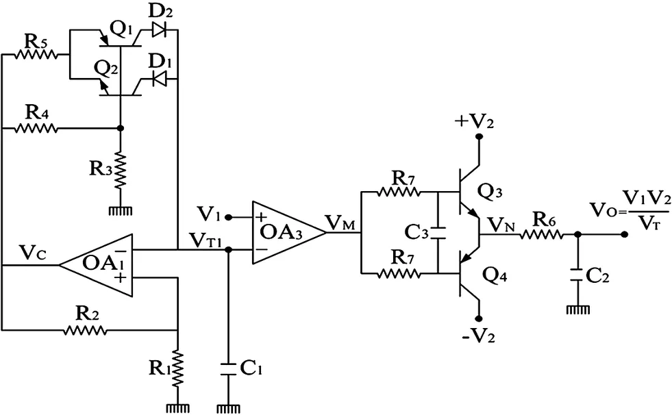
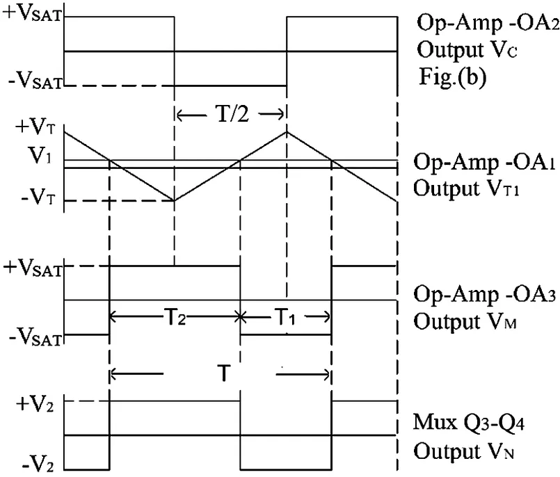
The circuit diagrams of triangular wave–based TDMs are shown in Figure 11.1, and their associated waveforms are shown in Figure 11.2. In Figure 11.1(a), a triangular wave VT1 with ±VT peak-to-peak value and time period ‘T’ is generated by the op-amp OA1 and transistors Q1 and Q2. The value of VT is given as
(11.1)

where β is given as and time period ‘T’ is given as
(11.2)
In Figure 11.1(b), op-amps OA1 and OA2 constitute a triangular/square wave generator. The output of op-amp OA1 is a triangular wave VT1 with ±VT peak values and time period ‘T’. Let initially the comparator OA2 output be LOW(−VSAT), and the integrator ouput composed by op-amp OA1, resistor R1, and capacitor C1 be given as
(11.3)
The integrator output is rising toward positive saturation, and when it reaches a value +VT, the comparator output becomes HIGH(+VSAT). The integrator output composed by op-amp OA1, resistor R1, and capacitor C1 is given as
...Table of contents
- Cover
- Half Title Page
- Title Page
- Copyright Page
- Dedication
- Contents
- Preface
- Useful Notations
- Abbreviations
- Introduction
- Part A Fundamentals of Function Circuits
- Part B Principles of Function Circuits
- Part C Design of Function Circuits
- Part D General on Function Circuits
- Part E Miscellaneous Function Circuits
- Part F Applications of Function Circuits
- Appendix A Analog Function Circuits Tutorial Kit
- Index
Frequently asked questions
Yes, you can cancel anytime from the Subscription tab in your account settings on the Perlego website. Your subscription will stay active until the end of your current billing period. Learn how to cancel your subscription
No, books cannot be downloaded as external files, such as PDFs, for use outside of Perlego. However, you can download books within the Perlego app for offline reading on mobile or tablet. Learn how to download books offline
Perlego offers two plans: Essential and Complete
- Essential is ideal for learners and professionals who enjoy exploring a wide range of subjects. Access the Essential Library with 800,000+ trusted titles and best-sellers across business, personal growth, and the humanities. Includes unlimited reading time and Standard Read Aloud voice.
- Complete: Perfect for advanced learners and researchers needing full, unrestricted access. Unlock 1.5M+ books across hundreds of subjects, including academic and specialized titles. The Complete Plan also includes advanced features like Premium Read Aloud and Research Assistant.
We are an online textbook subscription service, where you can get access to an entire online library for less than the price of a single book per month. With over 1.5 million books across 990+ topics, we’ve got you covered! Learn about our mission
Look out for the read-aloud symbol on your next book to see if you can listen to it. The read-aloud tool reads text aloud for you, highlighting the text as it is being read. You can pause it, speed it up and slow it down. Learn more about Read Aloud
Yes! You can use the Perlego app on both iOS and Android devices to read anytime, anywhere — even offline. Perfect for commutes or when you’re on the go.
Please note we cannot support devices running on iOS 13 and Android 7 or earlier. Learn more about using the app
Please note we cannot support devices running on iOS 13 and Android 7 or earlier. Learn more about using the app
Yes, you can access Analog Function Circuits by K. C. Selvam in PDF and/or ePUB format, as well as other popular books in Technology & Engineering & Electrical Engineering & Telecommunications. We have over 1.5 million books available in our catalogue for you to explore.