![]()
In the most generic sense, a drive is a device that controls speed, torque, direction, and the resulting horsepower of a system. There are many types of drives, and they will be discussed later in this chapter. For now, we will focus on the reasons drives are used in industrial and commercial environments. To appreciate the use and benefits of any type of drive, we must look at a generic application and determine how the system could be improved.
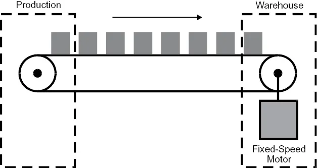
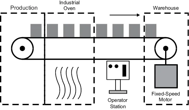
Figure 1-1 shows a prime candidate for a variable-speed drive: a conveyor in a manufacturing plant.
Figure 1-1. Generic conveyor system.
The figure shows that the main purpose of a conveyor is to move products from production to the warehouse. A typical way to move products is by means of a motor. The generic motor on this conveyor operates at only one speed. With only one speed of motion, this type of manufacturing system has its drawbacks.
The products can reach the warehouse only in a given time frame. There is no way to gradually increase the conveyor speed. If it takes the motor a very short time to accelerate, the boxes may fall off the conveyor because of the accelerating forces. Several factors lead to the use of a variable-speed drive: efficiency gains, process changes and improvements, and system coordination.
Efficiency Gains
We may view the system in Figure 1-1 as very inefficient. We are locked into whatever efficiencies the motor can provide, given a somewhat variable amount of loading. If the motor in Figure 1-1 happened to be an alternating current (AC) motor, the following would typically be true:
•The more load on the motor, the more efficient the motor is.
•The higher the motor’s horsepower rating, the higher the efficiency.
•The higher the operating speed, the more efficient the motor.
We will cover the physical makeup of AC and direct current (DC) motors in more detail in Chapter 3, “AC and DC Motors.” For now, we will use an AC motor to explain the effects of efficiency on the total system.
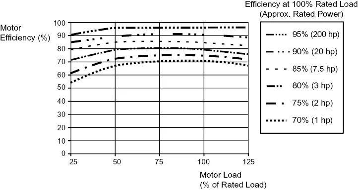
As shown in Figure 1-2, efficiencies vary.
Figure 1-2. Typical AC motor efficiencies.
If the conveyor motor happened to be 1 hp, we may expect to see only 70% efficiency, at 75%–100% motor load (% efficiency = output power ÷ input power × 100). By strict definition, the 1 hp AC conveyor motor would be operating at a 30% loss at 75%–100% motor load.
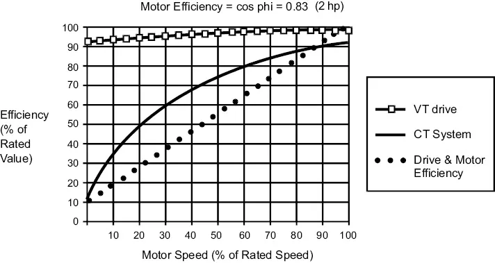
Figure 1-3 indicates AC drive and motor efficiencies at various speeds.
Figure 1-3. AC drive and motor efficiencies.
Figure 1-3 shows an example of a 2 hp system. In this example, if we added a variable-speed AC drive, the efficiency of this constant torque (CT) system would be in the range of 80%–90% when the conveyor is operated at 60% speed or higher. A conveyor is labeled a constant torque load and is indicated by CT on the graphs.
It should be noted that the AC drive is an efficient means of varying the speed of an AC motor. Its 5%–10% losses are attributed to thermal losses because the AC switches power devices several thousand times per second. Variable-speed output from a drive has a direct impact on the total system efficiency. A manufacturer can operate the production equipment at the most efficient speed and load point—if drive and motor efficiencies are known.
Process Changes and Improvements
As previously indicated, in a fixed system there is no way to vary the speed of the conveyor. A fixed system will not allow for changes in the process or production cycle. Some manufacturing circumstances may require a slow speed, whereas others need a faster pace.
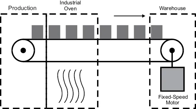
The same conveyor system illustrated in Figure 1-1 is used in processes such as baking. Figure 1-4 illustrates the same type of conveyor with the addition of an industrial oven.
Figure 1-4. Industrial oven used in production.
Certain materials may require a longer baking cycle because of thickness. If a fixed-speed motor is used, only one type of material could be processed in this system. To stay competitive, many companies require flexibility in manufacturing. Therefore, a variable-speed system is often necessary to change production cycle times and increase capacity.
System Coordination
The system shown in Figure 1-4 is typical of many manually operated processes. An operator turns on the system and then turns it off for maintenance or at the completion of the production cycle. However, in an age of increased flexibility requirements, few processes are manually operated. Production cycles are constantly monitored by some type of computer system.
Computer systems will automatically oversee the process and correct for load fluctuations, material density, and size requirements. In industrial processes, the use of programmable logic controllers (PLCs) is typical. A complete discussion of PLCs is beyond the scope of this book, but they will be addressed at various points. Figure 1-5 illustrates a conveyor system that is manually operated by a control station.
Figure 1-5. Manually controlled conveyor system.
PLCs work effectively in place of the manually controlled operator station. Automatic control of the motor could therefore be accomplished, but only STOP and START control in this case. Variable-speed drives would be effective in providing the flexibility and control needed by motors to meet almost any application requirements.
Drive Principles of Operation
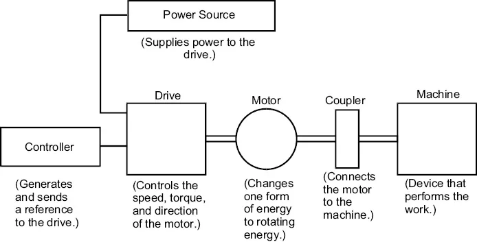
This section looks at a variable-speed drive system from a generic standpoint. All drive systems, whether electronic, mechanical, or fluid in nature, have the basic parts indicated in Figure 1-6.
Figure 1-6. Generic variable-speed drive system.
To understand a simple drive system, we will start at the end of the system and move backward. Individual sections of this book are devoted to each of the basic components listed in Figure 1-6. For now, the intent is to develop a basic understanding of a drive system. More complex concepts will be discussed in later chapters.
Machine
The essence of any drive system is the application, or machine. This is the heart of the system because it ultimately performs the work. The machine can be a conveyor, a press, a packaging machine, or literally hundreds of applications that operate at variable speed.
Coupler
The coupler is the device that connects the machine to the motor. Couplers come in all shapes and sizes. A coupler’s basic task is to make a solid connection between the motor and the machine. Couplers may accept one diameter of motor shaft and convert the output to another size shaft. In some cases, the coupler may be a device called a gearbox, which may include some type of speed-reducing or speed-increasing gears. Couplers can also be considered matching devices because of their ability to deliver power smoothly to the machine. To a certain extent, this device can also cushion shocks delivered by the motor to the machine.
Motor
This device changes one form of energy to rotating mechanical energy. It can be considered the prime mover because it takes power from the drive unit and translates it into motion. There are several types of motors using various forms of energy. In this book, we will discuss mechanical, hydraulic, AC, and DC motors. The size of the motor usually dictates the amount of rotating motion it can generate from incoming power. As explained later, there are a few exceptions to this principle.
Drive
The drive can be consi...