![]()
Chapter 1
Industrial Automation
and Control System
![]()
Position Control of Switched Reluctance Planar Motor Based on Fuzzy Control
Hua-Cai Lu*, Guang-Zheng Ruan and Teng-Fei Dou
College of Electrical Engineering, Anhui Polytechnic University,
Wuhu, 241000, China
1. Introduction
Switched Reluctance Planar Motor (SRPM) is a new type of motor, which has been developed and has been widely used in social production and life for the past few years [1]. Large thrust fluctuation of the motor itself and serious current issues such as nonlinear distortion, have brought difficulties to motor tracking control. Some scholars suggested that auto-disturbance rejection control to solve problems in the motor position control [2, 3], but the parameters not easily adjust of the method brings difficult to control strategy. PID controller is the most widely used method technique in industrial applications, but its not easy setting of parameters is its weakness [4, 5]. This article attempts the fuzzy PID controller. It suppresses the electromagnetism thrust force undulation through the force distribution function, and use the fuzzy PID controller carries on the position control to the electrical machinery. The research results are as the basis for further study of SRPM.
2. Establish the Mathematical Model
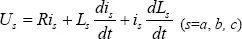
As the X and Y directions of the switched reluctance motor are the same, the electromagnetic properties of the X axis are analyzed in here. Eq. (1) describes the X-axis three phase rotor voltage:
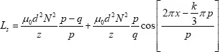
where Us is the voltage applied to the phase s of SRPM, is is the current applied to the phase s of the stator, Ls is the inductor applied to the phase s of the motor. Ls is described as Eq. (2):
where N is the number of windings, p is the polar distance, q is the groove width, z is the air gap. In Eq. (2), k is 0 when s describes a-phase, k is 2; when s describes b-phase, k is 4 when s describes c-phase.
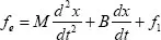
Due to SRPM is a nonlinear model, the model is described by
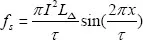
where fe is the electromechanical force, M is the mass, B is the friction, fl is external load force. Ignoring leakage inductance, the electromagnetic force can be expressed as
where LΔ is (Lmax – Lmin)/2, and Lmax is Maximum inductance, Lmin is minimum inductance.
3. Controller Design
3.1. PID control system
Eq. (5) shows that the SRPM of X, Y axis motion is a second-order system. Controller for second order systems can be designed according to the conventional PID controller design steps. Ignoring the friction force of the rail, the motor open-loop transfer function is
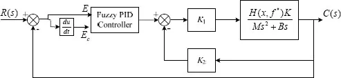
where K is 1000. In order to increasing the fast response of the system and reducing the system error, the system uses double closed loop design. The inner loop adopts proportional negative feedback, and the outer loop takes fuzzy PID controller. The concrete structure is shown in Figure 1. Assuming that the H (f*, x) is used for the distribution of the multi phase excitation, the open-loop transfer function of the motor can be further expressed as
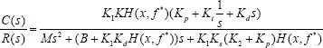
and system closed loop transfer function is
where Kp, Ki, Kd are respectively the proportional, integral, differential parameters of the PID controller. K1 is the forward channel coefficient, K2 is negative feedback coefficient. Eq. (7) shows that the system is a typical two order system. By adjusting the PID parameters, the system can be stable.
3.2. Fuzzy PID control system
Fuzzy PID control system is to have the system error E and the System Error change Ec the input of the fuzzy controller, and the PID controller coefficient Ki, Kd and Kp as the output of the fuzzy controller. After setting up fuzzy control rule library, the output of fuzzy controller is adjusted ...