- 544 pages
- English
- ePUB (mobile friendly)
- Available on iOS & Android
eBook - ePub
Tools to learn more effectively

Saving Books

Keyword Search

Annotating Text

Listen to it instead
Information
1 Introduction to digital electronic circuit
1.1 Introduction
Electronics is a branch of physics, engineering, and technology that deals with circuits consisting of components that control the flow of electricity. Circuits and components can be divided into two groups: analog and digital. A particular device may consist of circuitry that has analog or digital or a combination of these. Digital electronics or digital electronic circuits operate on digital signals. In the early days, applications of digital electronic circuits were focused on computer systems. Now digital electronics has been applied in a wide range of systems, such as telecommunication systems, military systems, medical systems, control systems, and consumer electronics. This chapter provides a broad overview of digital electronic circuits, including a brief introduction to the basic concepts of digital circuits, their commonly used devices, and technology of electronic design automation (EDA).
The objectives of this chapter are to
- – Explain the differences between digital and analog quantities
- – Describe the representation of digital quantities
- – Explain the classification of digital circuits
- – State the advantages of digital over analog
- – Explain the characteristics of the commonly used hardware description languages (HDLs)
- – Define EDA
- – Describe the design and programming process of programmable logic device (PLD)
1.2 Introductory basic concepts of digital electronic circuit
Electronic systems can be divided into two broad categories: digital and analog. Digital circuits are electric circuits that deal with the digital signals that have a number of discrete voltage levels. To most engineers, the terms “digital circuit,” “digital system,” and “logic” are interchangeable in the context of digital circuits, while analog circuits involve quantities with continuous values. This section introduces some basic concepts about digital circuits.
The objectives of this section are to
- – Explain the differences between digital and analog quantities
- – Define binary digits
- – Describe how to represent voltage levels by bits
- – Explain the advantages of digital circuits over analog circuits
1.2.1 Analog and digital
An analog quantity is the one having continuous values in time. A digital quantity is the one having a discrete set of values. In the natural world, most of the physical parameters, such as temperature, pressure, and strain, are analog quantities. These physical parameters can be converted into continuous electronic signals, voltage, or current, by the specific sensor so that they can be processed using the circuit. An analog signal refers to a signal that changes its value continuously over time. The typical analog signal is sinusoidal wave or sound wave, as shown in Figure 1.2.1(a). The term analog signal usually refers to electronic signals; however, mechanical, pneumatic, hydraulic, human speech, and other systems may also convey or be considered analog signals.
A digital signal refers to an electrical signal that has a sequence of discrete values; at any given time it can only take one of a finite number of values [1, 2]. This contrasts with an analog signal, which represents continuous values; at any given time it represents a real number within a continuous range of values. In digital circuit, a digital signal is a pulse train, that is, a sequence of fixed width electrical pulses. Figure 1.2.1(b) shows a typical digital signal that varies between low and high voltage levels, in which the high voltage level conveys a binary 1 and the low voltage level conveys a binary 0. This kind of digital signal is also called as a logic signal or a binary signal.

1.2.2 Binary digits, logic levels, and digital waveforms
1. Binary digits
Most digital circuits use a binary system that only has two digits, 1 and 0, which can represent two voltage levels. A binary digit is called a bit. Often logic “0” will be a lower voltage and referred to as “LOW” while logic “1” is referred to as “HIGH.” This is called positive logic and is used throughout this book.
Of course, you can use logic “0” representing a HIGH and logic “1” representing a LOW. This logic system is called negative logic.
In digital systems, a combination of 1s and 0s is called codes, which are used to represent numbers, symbols, alphabetic characters, and other types of information.
2. Logic levels
The voltage used to represent a 1 or a 0 are called logic level. In a practical digital circuit, a HIGH level can be any voltage level between a specified minimum value and a specified maximum value. Likewise, a LOW can be any voltage level between a specified minimum and a specified maximum. There is no overlap between the accepted range of HIGH and LOW levels.
3. Digital waveforms
Digital waveform consists of voltage levels that change back and forth between the HIGH and LOW levels. As shown in Figure 1.2.2, a positive-going pulse is generated when the voltage goes from its normally LOW level to its HIGH level. The negative-going pulse is formed when the voltage goes from its normally HIGH level to its LOW level.

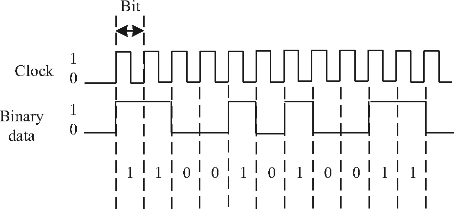
Binary information, handled by digital systems, appears as digital waveforms. A digital waveform is made up of a series of pulses, sometimes called pulse trains [3]. When the waveform is HIGH, a binary 1 is present; when the waveform is LOW, a binary 0 is present. Each bit in a sequence occupies a defined time interval called a bit time. In digital systems, signal waveforms are synchronized with a basic timing waveform called the clock, as shown in Figure 1.2.3. The waveform of the clock is a period of pulse trains in which the pulse period equals to a bit time. Binary data is indicated by the level in the waveform. During each bit time of the clock, waveform of binary data is either HIGH or LOW, in which HIGHs and LOWs represent a sequence of binary digits (bits). Binary data is represented by a group of several bits. Notice that the clock waveform itself does not carry information.
1.2.3 Characteristics of digital circuit
A digital circuit is a circuit that takes digital signals as inputs, processes them, and outputs the processed digital signals. Compared with analog circuits, digital circuits have some distinguished advantages.
Since a digital signal is a signal in which discrete steps are used to represent information, active components in digital circuits typically have one signal level when turned on, and another signal level when turned off. In general, a component in digital circuits is only switched on or off. For example, transistors in digital circuits operate either in saturation region or in cutoff region. While transistors in analog circuits operate in active region, their outputs are susceptible to several factors such as temperature, power supply voltage, and component aging. Therefore, an advantage of digital circuits when compared to analog circuits is that signals represented digitally can be transmitted without degradation due to noise [4].
Information storage can be designed easily in digital systems than in analog ones. The noise immunity of digital systems permits data to be stored and retrieved without degradation. In an analog system, noise from aging and wear degrades the stored information. In a digital system, as long as the total noise is below a certain level, the information can be recovered perfectly.
Digital circuits are the most common physical representation of Boolean algebra [5]. The design of digital circuits is a logical design that does not require designers to have very strong mathematical background, whereas the analog circuit design requires the calculation of the model in order to understand and study the internal characteristics and the operating principle of the circuit. In a digital system, a more precise representation of a signal can be obtained by using more binary digits to represent it. While this requires more digital circuits to process the signals, each digit is handled by the same kind of hardware, resulting in an easily scalable system. In an analog system, additional resolution requires fundamental improvements in the linearity and noise characteristics of each step of the signal chain.
Digital circuits are easy to be integrated, and they are low cost and small in size [6]. The integration level of digital circuits is generally higher than that of analog circuits. In addition, digital circuits are programmable. Computer language can be used to design some digital circuits to achieve corresponding logic functions. Computer-controlled digital systems can be controlled by software, allowing new functions to be added without changing hardware. Often this can be done outside the factory by updating the product’s software. So, the product’s design errors can be corrected after the product is in the customer’s hands.
1.3 Digital integrated circuits and typical packages
Digital electronic circuits are usually made from large assemblies of logic gates to implement various logic functions, which mainly involve combinational logic functions and sequential logic functions. All the logic elements and functions in a digital circuit are available in an integrated circuit (IC) form. A monolithic IC is an electronic circuit that is constructed entirely on a single small chip of silicon. All the components that make up the circuit – transistors, diodes, resistors, and capacitors – are an integral part of that single chip. Digital ICs are divided into two broad categories: fixed-functional logic and programmable logic. This section briefly introduces fixed-function devices, programmable logic devices (PLDs), and their typical packages.
The objectives of this section are to
- – Explain the difference between fixed-function logic devices and PLDs
- – Recognize the IC packages
- – Explain the ...
Table of contents
- Cover
- Title Page
- Copyright
- Preface
- Contents
- About the Authors
- 1 Introduction to digital electronic circuit
- 2 Number systems and codes
- 3 Boolean algebra and logic simplification
- 4 Combinational logic circuits
- 5 Flip-flops and related devices
- 6 Sequential logic circuits
- 7 Counters
- 8 Registers and shift registers
- 9 Semiconductor memory
- 10 Programmable logic device
- 11 Analog-to-digital and digital-to-analog converter
- 12 Integrated gate circuit
- Appendix I
- References
- Index
Frequently asked questions
Yes, you can cancel anytime from the Subscription tab in your account settings on the Perlego website. Your subscription will stay active until the end of your current billing period. Learn how to cancel your subscription
No, books cannot be downloaded as external files, such as PDFs, for use outside of Perlego. However, you can download books within the Perlego app for offline reading on mobile or tablet. Learn how to download books offline
Perlego offers two plans: Essential and Complete
- Essential is ideal for learners and professionals who enjoy exploring a wide range of subjects. Access the Essential Library with 800,000+ trusted titles and best-sellers across business, personal growth, and the humanities. Includes unlimited reading time and Standard Read Aloud voice.
- Complete: Perfect for advanced learners and researchers needing full, unrestricted access. Unlock 1.4M+ books across hundreds of subjects, including academic and specialized titles. The Complete Plan also includes advanced features like Premium Read Aloud and Research Assistant.
We are an online textbook subscription service, where you can get access to an entire online library for less than the price of a single book per month. With over 1 million books across 990+ topics, we’ve got you covered! Learn about our mission
Look out for the read-aloud symbol on your next book to see if you can listen to it. The read-aloud tool reads text aloud for you, highlighting the text as it is being read. You can pause it, speed it up and slow it down. Learn more about Read Aloud
Yes! You can use the Perlego app on both iOS and Android devices to read anytime, anywhere — even offline. Perfect for commutes or when you’re on the go.
Please note we cannot support devices running on iOS 13 and Android 7 or earlier. Learn more about using the app
Please note we cannot support devices running on iOS 13 and Android 7 or earlier. Learn more about using the app
Yes, you can access Digital Electronic Circuits by Shuqin Lou, Chunling Yang in PDF and/or ePUB format, as well as other popular books in Biological Sciences & Information Technology. We have over one million books available in our catalogue for you to explore.