![]()
1
Introduction
1.1 Verification Methods
For civil engineering structures the ultimate limit state (structural safety) and serviceability limit state have to be verified, see for example DIN 18800 Part 1. Since components for steel constructions are usually rather slender and thin-walled, structural safety verifications for constructions susceptible to losing stability regarding flexural, lateral torsional and plate buckling are of major significance and therefore constitute a main focal subject in static calculations. In this context, the determination of internal forces and moments, deformations and critical loads is a central task. Its solution is treated in this book using the finite element method (FEM).
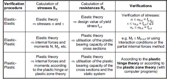
The calculations and verifications have to meet the legal requirements as well as the state of the art. For steel structures the basic standard DIN 18800 and corresponding engineering standards, or Eurocode 3, have to be taken into consideration. Table 1.1 contains a compilation of the verification methods according to DIN 18800 and the verifications as they are generally applied. Eurocode 3 contains similar regulations.
Table 1.1 Verification procedures according to DIN 18800 and common verifications
The use of a
verification method implies that the individual cross section parts (webs and flanges) can carry the compression stresses, so that no buckling occurs and a sufficient rotation capacity is provided. Assistance for the checking of the b/t relations can be found in profile tables; see for example [29]. If only longitudinal axial stresses and shear stresses occur, it is
. The verification of the
equivalent stress (
verification method Elastic-Elastic) is only required for σ/σ
R,d and τ/τ
R,d > 0.5. Perfectly plastic internal forces and moments for rolled sections can be found in profile tables [29], interaction conditions and verifications using the partial internal forces method in [29] and [25].
The subscript “d” for Sd and Rd in Table 1.1 indicates that the stresses must be determined using the design parameters of the loads and that the design resistance has to be applied; see Section 1.7. Section 1.4 “Linear and Nonlinear Calculations” includes specifications concerning the calculation of stress and resistance.
1.2 Methods to Determine the Internal Forces and Moments
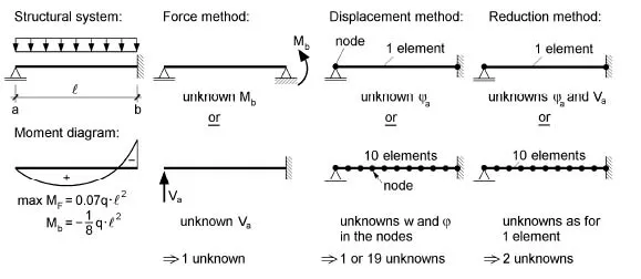
As it is generally known, internal forces and moments in statically determinate systems may be calculated with the help of equilibrium conditions and intersection methods. This is not possible with statically indeterminate systems and thus another solution procedure is used, such as the force method, which is the classical method of structural analysis. It is appropriate for hand calculation and very straightforward since it is easy to understand in engineering terms. However, the disadvantage is that for differing structural systems many approaches must be developed and, moreover, it is completely inappropriate for many tasks.
Figure 1.1 exemplifies a singlely indeterminate girder. Hence, when using the force method, one unknown force value must be defined. After this, the moment distribution can be determined using the equilibrium conditions. The basis of the method is always the choice of a statically determinate structure (primary structure). Since there are several possibilities for doing so, the two systems in Figure 1.1 are selected examples.
Generally, there are three methods for determining the internal forces and moments:
- Force method
- Displacement method → FEM
- Reduction method → FEM
Moreover, there are numerous variations within these three methods, which cannot be discussed in detail here. Whereas when using the force method, the forces are the unknown variables of the emerging equation system, when using the displacement method, the unknown variables are the displacements, i.e. the displacements and rotations. If the structural system is divided into finite elements (e.g. beam elements or segments), the displacement method is extremely appropriate for a generalised formulation and so is applicable in many different situations. The ideas involved are not simple in engineer terms but are very mathematical because large amounts of data must be handled with sizable equation systems solved. The actual amount of data and the size of the equation system will, of course, depend on the system under consideration, but it will certainly be more than would be needed for the force method.
Figure 1.1 shows the application of the displacement method. Using this method, the unknown values are the deformations at the nodes, i.e. for the examined beam the displacement w and the rotation φ. Thus, there are two unknowns per node, so depending on the geometric boundary conditions, there will be between one and 19 unknowns in each example. Using the FE model with 10 elements, a relatively large number of unknowns (19) occur, but there is no need of further hand calculation, which is an advantage. For procedural reasons, all state variables (bending moments, shear forces, displacements, rotations) at the nodes, i.e. virtually in the entire system, are determined.
Due to the numeric complexity, the widespread use of the FEM with the displacement method is closely connected to the rapid development of high-capacity computers. Until about 1985, it was important to model structures using finite elements in such a way that the limited memory capacity was sufficient and that computing times did not escalate. Nowadays, these considerations are only important for exceptional structures and calculations. Then again, it is often seen that in static calculations exaggeratedly fine FE-modelling or the use of inappropriate finite elements create reams of paper. As shown in Figure 1.1, it can be very reasonable to calculate a single-span beam using an FEM program, since all values for the necessary verifications are directly obtained by the program and the corresponding pages for the static calculation can be printed out with minimal effort.
The third method mentioned above is the reduction method, which is suitable for continuous beams including instance sharp bends. The unknowns of the resulting equation system are the unknown internal forces and displacements at the beginning of the beam structure (see Figure 1.1), so that for beams, a maximum of seven unknowns results. Accordingly, the require...