eBook - ePub
Cone Beam Computed Tomography in Endodontics
Shanon Patel, Simon Harvey, Hagay Shemesh, Conor Durack
This is a test
Compartir libro
- 493 páginas
- English
- ePUB (apto para móviles)
- Disponible en iOS y Android
eBook - ePub
Cone Beam Computed Tomography in Endodontics
Shanon Patel, Simon Harvey, Hagay Shemesh, Conor Durack
Detalles del libro
Vista previa del libro
Índice
Citas
Información del libro
In recent years, cone beam computed tomography (CBCT) has become much more widely available and utilised in all aspects of dentistry, including endodontics. Cone Beam Computed Tomography in Endodontics is designed to inform readers about the appropriate use of CBCT in endodontics, and enhance their clinical practice with this exciting imaging modality.
Preguntas frecuentes
¿Cómo cancelo mi suscripción?
¿Cómo descargo los libros?
Por el momento, todos nuestros libros ePub adaptables a dispositivos móviles se pueden descargar a través de la aplicación. La mayor parte de nuestros PDF también se puede descargar y ya estamos trabajando para que el resto también sea descargable. Obtén más información aquí.
¿En qué se diferencian los planes de precios?
Ambos planes te permiten acceder por completo a la biblioteca y a todas las funciones de Perlego. Las únicas diferencias son el precio y el período de suscripción: con el plan anual ahorrarás en torno a un 30 % en comparación con 12 meses de un plan mensual.
¿Qué es Perlego?
Somos un servicio de suscripción de libros de texto en línea que te permite acceder a toda una biblioteca en línea por menos de lo que cuesta un libro al mes. Con más de un millón de libros sobre más de 1000 categorías, ¡tenemos todo lo que necesitas! Obtén más información aquí.
¿Perlego ofrece la función de texto a voz?
Busca el símbolo de lectura en voz alta en tu próximo libro para ver si puedes escucharlo. La herramienta de lectura en voz alta lee el texto en voz alta por ti, resaltando el texto a medida que se lee. Puedes pausarla, acelerarla y ralentizarla. Obtén más información aquí.
¿Es Cone Beam Computed Tomography in Endodontics un PDF/ePUB en línea?
Sí, puedes acceder a Cone Beam Computed Tomography in Endodontics de Shanon Patel, Simon Harvey, Hagay Shemesh, Conor Durack en formato PDF o ePUB, así como a otros libros populares de Medicine y Dentistry. Tenemos más de un millón de libros disponibles en nuestro catálogo para que explores.
Información
Chapter 1
The Limitations of Conventional Radiography and Adjunct Imaging Techniques
Introduction
Radiographic assessment is essential in every aspect of endodontics, from diagnosis to the management and assessment of treatment outcome (Forsberg, 1987a, b; Patel et al, 2015). Intraoral periapical radiography has historically been accepted as the most appropriate imaging system in endodontics. However, conventional periapical images yield limited information, which can potentially have an impact on diagnosis and treatment planning.
The purpose of this chapter is to describe the limitations of conventional periapical radiography, and to discuss the relative advantages and disadvantages of alternative imaging techniques.
Limitations of conventional radiographic imaging
Superimposition of three-dimensional anatomy
Conventional radiography results in three-dimensional (3D) structures being superimposed and displayed as a two-dimensional (2D) image (Nance et al, 2000; Cohenca et al, 2007). The resulting image allows complex dentoalveolar anatomy to be visualised only in the mesiodistal (clinical) plane, and provides limited information of the dental anatomy in the buccolingual (non-clinical) plane.
Radiographic 2D images prevent accurate assessment of the spatial relationship of the roots, and associated periapical lesions, to the surrounding anatomy (Cotti and Campisi, 2004). In addition, the location, nature, and shape of variations within the root under investigation (e.g. root resorption) may be difficult to assess (Patel et al, 2007; Whaites and Drage, 2013a). Diagnostic information in the missing ‘third dimension’ is of relevance when planning for endodontic surgery (Velvart et al, 2001; Bornstein et al, 2011). Useful information may include the position and angulation of the root/s in relation to the cortical plate, the thickness of the cortical plate itself, and the relationship of the root/s to adjacent anatomical structures, such as the inferior alveolar nerve, mental foramen or maxillary sinus (Lofthag-Hansen et al, 2007).
Additional parallax radiographic images, taken by changing the horizontal and/or vertical angulation of the X-ray beam in relation to the area under examination (Figs 1-1 and 1-2), may be used to enhance assessment of the spatial relationships of the imaged anatomical structures (European Society of Endodontology, 2006; Davies et al, 2015). However, these additional images will still only provide limited information (Soğur et al, 2012; Kanagasingam et al, 2015).
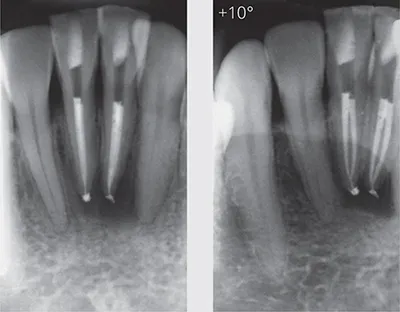
Fig 1-1 Horizontal parallax. The right radiograph has a 10-degree shift to aid visualisation of the two separate canals, which allows the quality of the root canal fillings to be assessed more accurately in the mandibular central incisors.

Fig 1-2 Vertical parallax. A vertical beam shift (change in inclination) has caused the periapical lesions (red arrows) associated with all three roots of this maxillary right first molar to disappear with the change of angulation in the right radiograph. Note that the defective distal margin on the left radiograph (yellow arrow) is also no longer visible on the right radiograph.
Geometric distortion
Intraoral periapical radiographic images should ideally be taken with a paralleling technique. The use of a biteblock to ensure the tooth and image receptor are parallel with one another, as well as the use of a beam aiming device to ensure the X-ray beam meets the tooth and image receptor at right angles, has been proven effective at creating a geometrically accurate image (Forsberg, 1987a, b, c).
An accurate image is obtained when the image receptor (X-ray film or digital sensor) is parallel to the long axis of the tooth, and the X-ray beam is perpendicular to both the image receptor and the tooth undergoing examination (Fig 1-3). This may be readily achievable in certain regions of the oral cavity, but may not be possible in some patients with e.g. small mouths or pronounced gag reflexes, and/or where the image receptor is poorly tolerated. Anatomical limitations, such as a shallow palatal vault, prevent the ideal positioning of the intraoral image receptor, causing incorrect long-axis orientation—which in turn results in geometric distortion (poor projection geometry) of the radiographic image (Figs 1-3 and 1-4). The ideal positioning of solid-state digital sensors may be even more challenging due to their size and rigidity, compared with conventional radiographic films and phosphor plate digital sensors (Patel et al, 2009a; Whaites and Drage, 2013a).
Ideal positioning of the image receptor may be possible when, firstly, the roots being imaged are relatively straight and, secondly, when there is sufficient space to position the image receptor correctly. If these objectives are not achieved (Fig 1-5), there will be a degree of geometric distortion and magnification. This may be particularly relevant in the posterior maxilla (Lofthag-Hansen et al, 2007). Over- or underangulated radiographs may reduce or increase the ‘apparent’ radiographic root length of the tooth under investigation (White and Pharaoh, 2014), and increase or decrease the size, or even result in the disappearance, of periapical lesions (Bender and Seltzer, 1961a, b; Huumonen and Ørstavik, 2002). A minimum 5% magnification of the imaged structures will occur, even when a ‘textbook’ paralleling technique has been employed (Vande Voorde and Bjorndahl, 1969).
Anatomical noise
Anatomical features within or superimposed over the roots being examined may obscure the area of interest, thereby preventing a thorough assessment of the imaged region (Gröndahl and Huumonen, 2004). These anatomical structures vary in radiodensity, and may be radiopaque or radiolucent. This phenomenon is sometimes referred to as ‘anatomical noise’ (Fig 1-6). The more complex the anatomical noise, the greater the reduction in contrast within the area of interest. The resulting radiographic image may be more difficult to interpret.
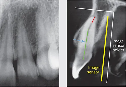
Fig 1-3 Geometric distortion. Although it may be possible to position the image sensor holder (and image sensor) parallel with the long axis of the crown and mid-third of the root, it is not possible to obtain a parallel relationship of the long axis of the entire tooth and root with the image sensor. The sagittal reconstructed CBCT image shows a parallel (and accurate) relationship of the mid-third root (green line) and the image sensor, and perpendicular X-ray beam (blue arrow). However, the apical third (red line) is not parallel to the image sensor or perpendicular to the X-ray beam, resulting in geometric distortion of the apical third of the root canal.

Fig 1-4 Geometric distortion. A distolingual canal (yellow arrow) can be seen on the intraoral radiograph (left). A coronal reconstructed CBCT image (right) clearly demonstrates how the distolingual root cannot be accurately assessed in the radiographic image. Neither the coronal (red line) nor apical (green line) halves of this root canal are parallel to the image sensor (yellow arrow), or perpendicular to the X-ray beam (blue arrow). This results in significant geometric distortion in this region of the image.
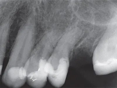
Fig 1-5 Geometric distortion. It may not be possible to position the image sensor in the ideal position, resulting in distortion of the resulting image. When imaging these maxillary left premolar teeth, the anatomical constraints of a shallow palate have prevented a paralleled image from being obtained.
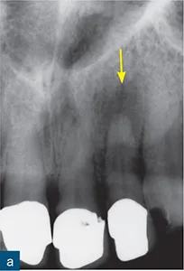
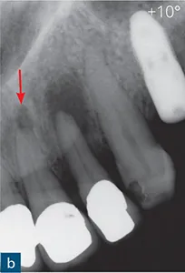
Fig 1-6 Anatomical noise. (a) A periapical radiolucency is clearly seen, and is associated with the maxillary left incisor (yellow arrow). (b) A second radiograph taken at a 10-degree horizontal shift reveals an additional periapical radiolucency (red arrow) associated with the maxillary left incisor. This ‘new’ radiolucency is the incisive foramen, which in this case creates radiolucent anatomical noise mimicking a periapical lesion.

Fig 1-7 Anatomical noise. The superimposition of anatomical structures prevents complete and accurate assessment of the imaged teeth. As demonstrated in these parallax periapical radiographs, the maxillary sinus and zygomatic buttress may often create anatomical noise, which prevents visualisation of the periapical regions of the maxillary premolar and molar teeth.
Brynolf (1967, 1970a, b) demonstrated that superimposition of the incisive canal over the apices of the maxillary central incisors may complicate radiographic interpretation, i.e. the incisive foramen (anatomical noise) mimicked periapical lesions in healthy teeth.
Several studies have shown that periapical lesions confined to the cancellous bone may not be detected with conventional radiographic imaging (Bender and Seltzer, 1961a, b). It has been suggested that periapical lesions may be successfully detected when confined to cancellous bone, provided the cortical bone is thin and the anatomical noise minimal. Such lesions may go undetected beneath a thicker cortex. Anatomical noise also accounts for some underestimation of periapical lesion...