![]() Ontology, semantic web and linked data
Ontology, semantic web and linked data![]()
A novel workflow to combine BIM and linked data for existing buildings
M. Bonduel, M. Vergauwen & R. Klein
Department of Civil Engineering, Technology Cluster Construction, KU Leuven, Ghent, Belgium
M.H. Rasmussen
Department of Civil Engineering, Technical University of Denmark, Kgs. Lyngby, Denmark
P. Pauwels
Department of Architecture and Urban Planning, Ghent University, Ghent, Belgium
ABSTRACT: Combining conventional Building Information Modeling (BIM) tools and Linked Data technologies improves the options to connect building models to external datasets. Existing workflows in this regard expect a conventional BIM model—including object’s geometry—as a starting point. This paper presents a novel, alternative workflow oriented towards existing buildings, including an initial implementation. Modeling the building topology using the BOT ontology is done first, allowing a Linked Data modeler to enrich this initial graph from the start of a project without being dependent on a BIM with (detailed) geometry. Later, a conventional BIM—including objects’ geometry—of the existing building can be made, starting from the shared building topology. At the end of this more flexible workflow, both the initial RDF graph and the BIM-based RDF graph are directly connected to each other, combining both datasets.
1 INTRODUCTION
1.1 BIM, linked data and linked building data
The acronym BIM or Building Information Model(ing) has multiple definitions depending on the context in which it is used. In its broadest sense, it is a concept where a database of a building is created, by defining the building elements and their semantics such as the classification of elements, element properties and relations towards other objects. When applying this broad vision, geometry becomes an optional property and is no strict requirement to define something as BIM. In this paper, the term ‘geometric BIM’ will be used to denote a building database where (3D) geometry and semantics are combined. Conventional BIM authoring tools such as Revit, Tekla, Archi-CAD, etc. are all examples of geometric BIM software. Such tools typically use a proprietary data schema to structure building information. In order to improve data exchange between different conventional BIM tools, buildingSMART International published several ISO standards, such as IFC (Industry Foundation Classes), IDM (Information Delivery Manual) and IFD (International Framework for Dictionaries). The IFC standard defines an open data schema and neutral format for BIM models, respectively based on EXPRESS and SPFF (Step Physical File Format).
Linked Data has its origins in the Semantic Web domain and is based on several W3C standards such as RDF (Resource Description Framework), SPARQL (SPARQL Protocol and RDF Query Language) and vocabulary/ontology languages such as RDFS (RDF Schema) and OWL (Web Ontology Language). Linked Data in essence consists of RDF triples with a subject node, predicate (relation) and object node, forming a directed graph. The subject and object node can be defined by a URI (Uniform Resource Identifier) or a so-called blank node. The object node can also be a literal value, while the predicate is always a URI. These RDF triples form a data layer (Abox) containing the actual data instances, and a terminology layer (Tbox) based on the applied ontologies. Reasoning engines can be used to infer implicit knowledge based on the used ontologies in a standardized manner.
The principles of Linked Data are used in a broad range of knowledge domains to create and use data via the web that is both human and machine readable. Because of its basic principles, it is extremely well suited to connect elements of different datasets. Linked Building Data (LBD) is the application of Linked Data in the building domain. Initial research in the LBD domain was mainly oriented towards conventional BIM, and more specifically the conversion of the neutral IFC schema into an ifcOWL Linked Data ontology (Pauwels & Terkaj 2016). New initiatives emerged to make the ifcOWL ontology better suited for usage in Linked Data applications, by adhering best practices from the semantic web. Within the W3C LBD Community Group, the Building Topology Ontology or BOT1 was created, to serve as a central building ontology where other modular ontologies can relate to (Rasmussen, Pauwels, et al., unpubl.). The BOT ontology defines classes for spatial zones (bot:Site, bot:Building, bot:Storey and bot:Space) and building elements (bot:Element), topological relations between instances of these classes and some constraints on the usage of these classes and properties. Following BOT, both the development of an ontology for building products (PRODUCT2) and for building-related properties (PROPS3) has been initiated within the same W3C group. Using these new LBD ontologies, it becomes easier to create and use Linked Data Abox graphs of buildings as query writing is simplified significantly (Bonduel et al., in press). An LBD Abox graph can be defined as BIM if the earlier mentioned broad definition is used, even if a graph does not contain any geometry of the building elements.
1.2 Existing workflows for combining linked data and BIM
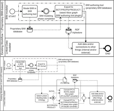
In literature, three implicit workflows exist for combining Linked Building Data (LBD) and conventional BIM data, either available in proprietary or neutral, standardized data formats. These workflows all start with the creation of a conventional BIM model, including often detailed geometry, which is afterwards converted into a Linked Data Abox graph. Following the workflow in the BPMN process map of Figure 1a, the proprietary BIM data is converted to Linked Data with a dedicated converter plugin for the BIM authoring tool. A limited demo implementation of such a workflow is demonstrated in (Rasmussen, Hviid, et al. unpubl.) for Autodesk Revit and the BOT ontology.
The BPMN (Business Process Model and Notation) standardized process map in Figure 1b depicts two other workflows, where the proprietary BIM data is first exported to the IFC format, which is then converted to an ifcOWL-or BOT/ PROPS/PRODUCT-based Abox graph, using respectively the IFC-to-RDF4 or IFCtoLBD5 converter (Bonduel et al. 2018). In the first work-flow (Fig. 1a), a new, software specific plugin has to be made and maintained for every BIM authoring tool. The intermediate step via IFC used in workflow two and three (Fig. 1b) means an extra conversion step (proprietary BIM to IFC, and IFC to RDF Abox graph) and thus an increased chance for conversion errors. The first approach however, remains closer to the original data source and is therefore preferred over the other approaches via IFC. From a practical point of view, the two workflows using IFC can be used directly in practice as all necessary tools and mappings already exist. In general, challenges to map the internal data scheme of the proprietary BIM software to the Linked Data counterpart defined in the used ontologies, might occur in all three workflows.
Figure 1. Existing workflows to combine BIM and Linked Data (above: workflow 1, below: workflow 2 and 3).
1.3 Data management for existing buildings
Current conventional BIM modeling tools are typically oriented towards newly built projects, and are less suited for modeling existing buildings, with their irregular geometries and specific elements (Volk et al. 2014). Modeling an existing construction in conventional BIM tools, often demands a survey campaign to assemble accurate geometric information reflecting the as-is state of the building, before the BIM modeling can start. In everyday practice, the above can have a serious impact on the price and time to complete a conventional BIM of an existing building. Therefore, multiple researchers investigate the automation of the BIM modeling process based on survey data, e.g. scan-to-BIM focusing on the automatic conversion of point clouds to BIM geometry (Volk et al. 2014).
The three earlier described workflows to combine BIM and Linked Data are all dependent on the availability of this geometric BIM, while it could be useful to start describing the building topology, individual building elements and their properties without having to care for the geometry of the building objects. Such a workflow would allow Linked Data modelers to reconstruct the building’s topology and to connect it with general information, historical, geographic, public authorities’, sensor and material Linked Data, as well as existing files such as 2D plans and photographs. In this way, a non-geometric BIM is created. When at a certain moment, the need arises to create a geometrical BIM, it should be possible to connect the elements of the earlier created RDF graph to the corresponding instances of the BIM-derived RDF graph. Additionally, it makes sense to reuse the modeled building topology from the initial graph, while creating the geometric BIM.
The subject of this study, is to propose a novel and flexible workflow for combining Linked Data and BIM, and is supported by the implementation of (1) a web application to create a Linked Building Data graph and (2) a plugin for a conventional BIM authoring tool to use the building topology of the initial graph as a template while modeling the geometric BIM. The same plugin also assists the user to connect each geometric BIM object to its counterpart in the initial RDF graph.
2 A NOVEL WORKFLOW FOR COMBINING LINKED DATA AND BIM
2.1 Proposal for a new workflow
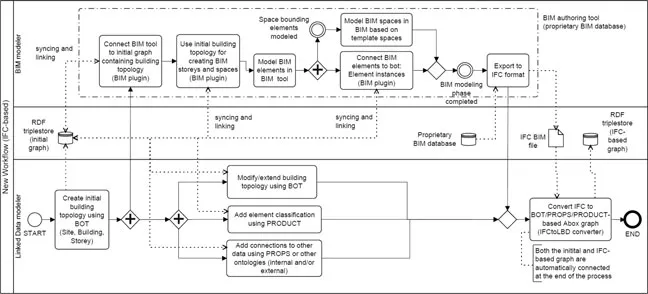
The new workflow is documented in a BPMN process map (Fig. 2) and clearly visualizes the fact that the Linked Data modeler and the (geometric) the building topology is synchronized between both environments. As the complex and elaborated ifcOWL ontology is not very practical to create a graph of the building topology (Terkaj & Pauwels 2017), the earlier mentioned BOT ontology was selected for this workflow, supported by the emerging PROPS and PRODUCT ontologies.
Figure 2. Novel workflow for combining linked data and BIM.
The Linked Data modeler starts with defining the building topology using BOT (site, building, storeys, spaces and elements). Note that not all bot:Element instances have to be defined in this graph, but only the ones that will be used during the Linked Data enr...