![]()
1
P. Bézier
How a Simple System Was Born
In order to solve CAD/CAM mathematical problems, many solutions have been offered, each adapted to specific matters. Most of the systems have been invented by mathematicians, but UNISURF was developed by mechanical engineers from the automotive industry who were familiar with parts mainly described by lines and circles. Fillets and other blending auxiliary surfaces were scantly defined; their final shape was left to the skill and experience of patternmakers and die-setters.
Around 1960, designers of stamped parts, that is, car-body panels, used french curves and sweeps, but in fact, the final standard was the “master model,” the shape of which, for many valid reasons, could not coincide with the curves traced on the drawing board. This resulted in discussions, arguments, haggling, retouches, expenses, and delay.
Obviously, no significant improvement could be expected so long as a method was not devised that could prove an accurate, complete, and undisputable definition of freeform shapes.
Computing and numerical control (NC), at that time, had made great progress, and it was certain that only numbers, transmitted from drawing office to tool drawing office, manufacturing, patternshop, and inspection could provide an answer; of course, drawings would remain necessary, but they would only be explanatory, their accuracy having no importance, and numbers being the only and final definition.
Certainly, no system could be devised without the help of mathematics—yet designers, who would be in charge of operating it, had a good knowledge of geometry, especially descriptive geometry, but no basic training in algebra or analysis.
In France, at that time, very little was known about the work performed in the American aircraft industry; the papers from James Ferguson were not much displayed before 1964; Citroen was secretive about the results obtained by Paul de Casteljau, and the famous technical report MAC-TR-41 (by S. A. Coons) did not appear before 1967; The works of W. Gordon and R. Riesenfeld were printed in 1974.
At the beginning, the idea of UNISURF was oriented toward geometry rather than analysis, but with the idea that every datum should be exclusively expressed by numbers.
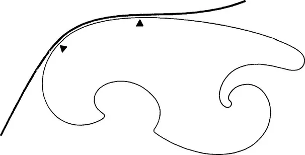
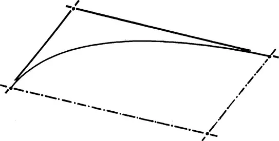
For instance, an arc of a curve could be represented (Figure 1.1) by the coordinates, cartesian, of course, of its limit points (A and B), together with their curvilinear abscissae, related with a grid traced on the edge.
Figure 1.1 An arc of a hand-drawn curve is approximated by a part of a template.
The shape of the middle line of a sweep is a cube, if its cross section is constant, its matter is homogeneous, and neglecting the effect of friction on the tracing cloth. However, it is difficult to take into account the length between endpoints; moreover, the curves employed for software for NC machine tools, that is, 2D milling machines, were lines and circles, and sometimes, parabolas. Hence, a spline shape should be divided and subdivided into small arcs of circles put end to end.
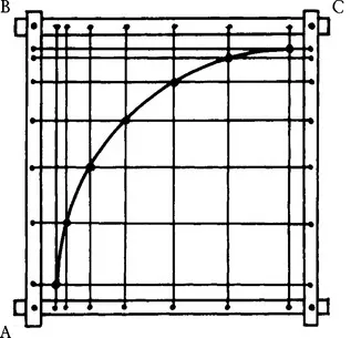
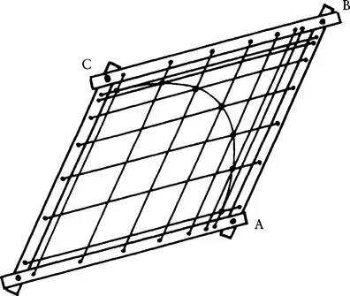
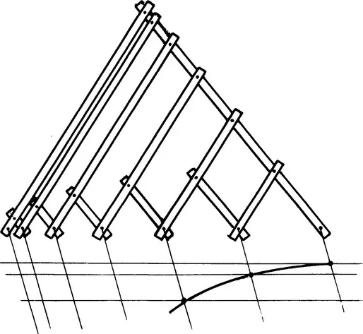
To transform an arc of circle into a portion of an ellipse, imagine (Figure 1.2) a square frame containing two sets of strings, whose intersections would be located on an arc of a circle; the frame sides being hinged, the square is transformed into a diamond (Figure 1.3), and the circle becomes an arc of an ellipse, which would be entirely defined as soon as the coordinates of points A, B, and C were known; if the hinged sides of the frame were replaced by pantographs (Figure 1.4), the diamond would become a parallelogram, and the definition of the arc of ellipse still results from the coordinates of the three points A, B, and C (Figure 1.5).
Figure 1.2 A circular arc is obtained by connecting the points in this rectangular grid.
Figure 1.3 If the frame from the previous figure is sheared, an arc of an ellipse is obtained.
Figure 1.4 Pantograph construction of an arc of an ellipse.
Figure 1.5 A “control polygon” for an arc of an ellipse.
Of course, this idea was not realistic, but it was easily replaced by the computation of coordinates of successive points of the curve. Harmonic functions were available with the help of analog computers, which were widely used at that time and gave excellent results.
But employing only arcs of ellipses limited by conjugate diameters was far too restrictive, and a more flexible definition was required.
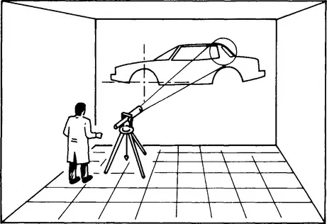
Another idea came from the practice of a speaker projecting, with a flashlight, a small sign, cross, or arrow, onto a screen displaying a figure printed on a slide. Replacing the arrow with a curve and recording the exact location and orientation of the flashlight (Figure 1.6) would define the image of the curve projected on the wall of the drawing office. One could even imagine having a variety of slides, each of which would bear a specific curve: circle, parabola, astroid, and so on.
Figure 1.6 A projector producing a “template curve” on the drawing of an object.
Of course, this was not a realistic idea because the focal plane of the zoom would seldom be square to the axis—an optician’s nightmare! But the principle could be translated, via projective geometry and matrix computation, into cartesian coordinates.
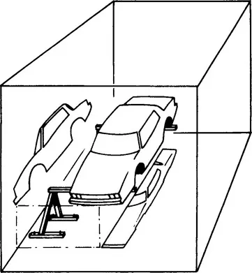
At that time, designers defined the shape of a car body by cross sections located 100 mm apart, and sometimes less. The advantage was that, from a drawing, one could derive templates for adjusting a clay model, a master, or a stamping tool. The drawback was that a stylist does not define a shape by cross sections but with so-called character lines, which seldom are plane curves. Hence, a good system should be able to manipulate and define directly “space curves” or “freeform curves.” Of course, one could imagine working alternately (Figure 1.7) on two projections of a space curve, but it is very unlikely that a stylist would accept such a solution.
Figure 1.7 Two imaginary projections of a car.
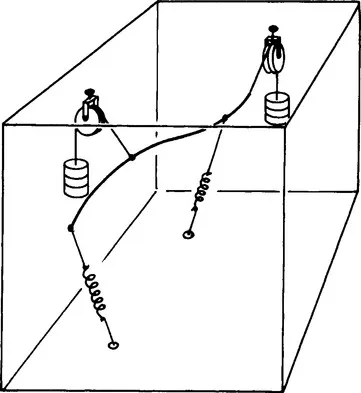
Theoretically as least, a space curve could be expressed by a sweep having a circular section, constrained by springs or counterweights (Figure 1.8), but this would prove quite impractical.
Figure 1.8 A curve held by springs.
Would it not be best to revert to the basic idea of a frame? But instead of a curve inscribed in a square, it would be located in a cube (Figure 1.9) that could become any parallelepiped (Figure 1.10) by a linear transformation that is easy to compute. The first idea was to choose a basic curve that would be the intersection of two circular cylinders; the parallelepiped would be defined by points O, X, Y, a...