Physics
Optical Encoder
An optical encoder is a device that converts motion or position into a series of digital signals using light. It typically consists of a light source, a patterned disc, and a sensor to detect the light patterns. As the disc rotates, the sensor detects the changes in light patterns, allowing the encoder to determine the position or motion of the object it is attached to.
Written by Perlego with AI-assistance
Related key terms
1 of 5
8 Key excerpts on "Optical Encoder"
- Hubert Razik(Author)
- 2013(Publication Date)
- Wiley-ISTE(Publisher)
Let us approach the measurement aspect of the angular position of a mechanical shaft, then its rotation speed. For this, two categories of coders exist: one is optical and the other is electromagnetic.1.1. Optical Encoder
Different types of optical coders exist. Certain ones have many advantages and others fewer, along with the inherent constraints of the choice of technology used. For this reason, we will first cover the measurement of the absolute position and second the measurement of the relative position of the mechanical shaft.1.1.1. Technical aspect
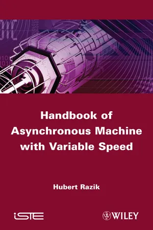
What is an Optical Encoder?An Optical Encoder is a system that allows us to provide logic level transitions 1 and 0 depending on the mechanical rotation. It consists of a disc with cuts similar to a multitude of lines that allow light to pass though. In this way a beam of light will excite a receiver, which will provide either level 1, or level 0 transitions after transformation of the collected signals. Figure 1.2 is a synoptic diagram of an Optical Encoder where we can discern the disc itself with it axis of revolution, light emitter, receiver and space letting the beam of light pass through.The Optical Encoder is free of restraints, since mechanical disturbances interfere with its lifespan and its performance. For this reason overspeeds are not allowed, since this will destroy the cuttings as well as causing mechanical vibrations that will vibrate the disc, bringing it into involuntary contact with the receiver or the emitter. In both cases, the defect encountered is irreversible since the cutting is affected by an anomaly. Before mentioning some of the defects of encoders, let us now look at the different types of Optical Encoders, starting with the absolute encoder.Figure 1.2.Representative diagram of an Optical Encoder1.1.2. Absolute encoder
The advantage of this encoder is to provide precise information of the angular position since, during the operation of the sensor, it is the real position of the shaft that is provided. Nevertheless, for problems of cutting quality, only the Gray code is recommended. In fact, there is one and only one transition of logic state: 0 to 1 or 1 to 0. This is not the case for classic binary code. For the purposes of structural comparison, Figure 1.3(a) shows the said relative absolute encoder and Figure 1.3(b) the Gray encoder. The angular representation is given in Table 1.1 eBook - ePub
- Paul P.L. Regtien, Edwin Dertien(Authors)
- 2018(Publication Date)
- Elsevier(Publisher)
The optical sensors described in this section are digital in nature. They convert, through an optical intermediate, the measurement quantity into a binary signal, representing a binary coded measurement value. Sensor types that belong to this category are Optical Encoders, designed for measuring linear and angular displacement, optical tachometers (measuring angular speed or the number of revolutions per unit of time) and optical bar code systems for identification purposes.Optical Encoders are composed of a light source, a light sensor and a coding device (much the same as the general setup in Fig. 7.1 ). The coding device consists of a flat strip for linear displacement or disk for angular displacement, containing a pattern of alternating opaque and transparent segments (the transmission mode) or alternating reflective and absorbing segments (the reflection mode). Both cases are illustrated in Fig. 7.12 .Figure 7.12 Optical Encoders in (A) transmission mode and (B) reflection mode.The coding device can move relatively to the assembly of transmitter and receiver causing the radiant transfer between them switch between a high and a low value. In the transmission mode the encoder consists either of a translucent material (e.g., glass, plastic, and mylar), covered with a pattern of an opaque material (for instance a metallization), or just the reverse, for instance a metal plate with slots or holes.Two basic encoder types are distinguished: absolute and incremental encoders. An absolute encoder gives instantaneous information about the absolute displacement or the angular position. Fig. 7.13 gives examples of absolute encoder devices in transmission mode.Figure 7.13 Absolute encoders: (A) linear encoders with 4-bit dual code and with 4-bit gray code, (B) readout system with collimator, and (C) angular encoder disc.Each (discrete) position corresponds to a unique code, which is obtained by an optical readout system that is basically a multiple version of Fig. 7.12A . The acquisition of absolute position with a resolution of n bits requires at least n optical tracks on the encoder and n eBook - ePub
Sensor Systems
Fundamentals and Applications
- Clarence W. de Silva(Author)
- 2016(Publication Date)
- CRC Press(Publisher)
The other three approaches may be used in special circumstances, where the optical method may not be suitable (e.g., under extreme temperatures or in the presence of dust, smoke) or may be redundant (e.g., where a code disk such as a toothed wheel is already available as an integral part of the moving member). For a given type of encoder (incremental or absolute), the method of signal interpretation is identical for all four types of signal generation listed previously. Now, we briefly describe the principle of signal generation for all four techniques and consider only the Optical Encoder in the context of signal interpretation and processing. 11.2.1.1.1 Optical Encoder The Optical Encoder uses an opaque disk (code disk) that has one or more circular tracks, with some pattern (sequence) of identical transparent windows (slits) in each track. A parallel beam of light (e.g., from a set of light-emitting diodes [LEDs]) is projected to all tracks from one side of the disk. The transmitted light is picked off using a bank of photosensors on the other side of the disk, which typically has one photosensor for each track. This arrangement is shown in Figure 11.2a, which indicates just one track and one pickoff sensor. The light sensor could be a silicon photodiode or a phototransistor (see Chapter 10). Since the light from the source is interrupted by the opaque regions of the track, the output signal from the photosensor is a series of voltage pulses. This signal can be interpreted (e.g., through edge detection or level detection) to obtain the increments in the angular position and also the angular velocity of the disk. In standard terminology, the sensor element of such a measuring device is the encoder disk, which is connected to the rotating object (directly or through a gear mechanism) eBook - PDF
- Wei Gao, Yuki Shimizu(Authors)
- 2021(Publication Date)
- De Gruyter(Publisher)
This is a serious problem for measurement of precision stages used in indus- tries since most of such stages are operated in the air. An Optical Encoder is another well-used sensor for measurement of stage displacement [14–16]. In an optical linear encoder, an optical sensor head is employed to read the physical graduations of a linear scale grating, from which the X-directional displacement of the scale grating with respect to the optical sensor head can be measured. Because the length of the optical path in an Optical Encoder, which is basically twice the gap between the optical sensor head and the scale sur- face, is small and constant, the Optical Encoder is more robust to environmental var- iations compared with the laser interferometer. This is an important advantage for industrial applications. The linear encoder has been expanded for two-axis mea- surement of the X-directional position and Y- or Z-directional error motion by using linear scale grating [17, 18]. Two-axis XY planar encoders have also been developed for measurement of the X- and Y-directional positions by using an XY planar scale grating with X- and Y-directional grating structures [19–22]. In an XY planar en- coder, a laser beam from the optical sensor head is projected onto the moving scale grating. The X-directional positive and negative first-order diffracted beams from the scale grating interference with each other to generate interference signals, from which the X-directional displacement can be obtained. Similarly, the Y-directional displacement can be obtained from the interference between the Y-directional positive and negative first-order diffracted beams from the scale grating. The XY planar en- coder has been successfully used for two-axis XY position measurement of CNC (com- puterized numerical control) machine tools [23] and photolithography scanners [24]. eBook - ePub
- David Nyce(Author)
- 2023(Publication Date)
- CRC Press(Publisher)
13 EncodersDOI: 10.1201/9781003368991-1313.1 Linear and Rotary
Linear and rotary position or displacement can be measured and communicated by a device called an encoder without using any form of analog-to-digital (A/D) conversion, because the basic output signal is already in a digital format. Although the term encoder has also been applied to devices based on Moiré patterns from diffraction gratings, as well as laser interferometers, the terms encoder, linear encoder, and rotary encoder will be used here in reference to standard industrial sensors based on geometric patterns applied along a linear, angular, or circular scale and detected by any one of several methods. Encoders are available as incremental or absolute reading, and encompass various detection techniques, including brush-type, optical, magnetic, and capacitive types. The most common detection methods for industrial encoders are magnetic and optical. Besides selecting whether the output will be absolute or incremental, encoder designers make trade-offs among important product features, including ruggedness, resolution, physical size, and cost.13.2 History of Encoders
The earliest type of encoder was the brush-type, a linear version of which is depicted in Figure 13.1 . In the figure, flexible mechanical contact fingers rub along a metal pattern printed onto an insulating base. The path of the brush moves over conducting and insulating segments. The conductor pattern is formed onto the base in the same way as printed circuit boards are made for connecting electronic circuits.The figure shows a straight binary code. An alternative, the Gray code, is explained later in this chapter. In the figure, the brush holder and four brushes (flexible metallic contact brushes) move along a left-to-right measuring axis. Dark segments represent the electrically conductive areas that would normally be connected to a positive voltage, such as +3.3 or +5 volts DC, to represent a logic one. Light areas are insulated or not electrically connected, and represent a logic zero. So, when a brush is on a light area, the signal from that brush is at logic zero (zero volts), and when a brush is on a dark area, the signal from that brush is at logic one (+3.3 or +5 volts). The brush holder shown is an insulating material, so wires can be connected with each brush to bring their voltages to a measurement or readout circuit. With the brushes in their rightmost position as shown, all four are at logic one, and indicate binary 1111, or decimal 15 (or hexadecimal F). At the leftmost position, binary 0000, or decimal 0 would be indicated. As the brushes move to the right from zero, the indicated position increments by 1 for each new position. These positions can be called digital positions zero through fifteen, or numeral positions one through sixteen. This simple pictorial, having only 4 bits, is shown for simplicity. Normal encoders will usually have at least eight, and up to 18 bits. Eight bits can indicate positions 0 through 255, for a resolution of about 0.4% (that is 100% × 1/256), while 18 bits can indicate 0 through 262,143 (note: 218 eBook - PDF
Mechatronics
A Foundation Course
- Clarence W. de Silva(Author)
- 2010(Publication Date)
- CRC Press(Publisher)
6.13.4 Absolute Optical Encoders An absolute encoder directly generates a coded digital word to represent each discrete angular position (sector) of its code disk. This is accomplished by producing a set of pulse signals (data channels) equal in number to the word size (number of bits) of the reading. Unlike with an incremental encoder, no pulse counting is involved. An absolute encoder may use various techniques (e.g., optical, sliding contact, magnetic saturation, proximity sensor) to generate the sensor signal, as for an incremental encoder. The optical method, which uses a code disk with transparent and opaque regions and pairs of light sources and photosensors, is the most common technique. A simplified code pattern on the disk of an absolute encoder that utilizes the direct binary code is shown in Figure 6.52a. The number of tracks ( n ) in this case is 4, but in practice n is 430 Mechatronics: A Foundation Course on the order of 14, but may be as high as 22. The disk is divided into 2 n sectors. Each parti-tioned area of the matrix thus formed corresponds to a bit of data. For example, a transpar-ent area will correspond to binary 1 and an opaque area will correspond to binary 0. Each track has a pick-off sensor similar to what is used in incremental encoders. The set of n pick-off sensors is arranged along a radial line and is facing the tracks on one side of the disk. A light source (e.g., LED) illuminates the other side of the disk. As the disk rotates, the bank of pick-off sensors generates pulse signals that are sent to n parallel data channels (or pins). At a given instant, the particular combination of signal levels in the data channels will provide a coded data word that uniquely determines the position of the disk at that time. 6.13.4.1 Gray Coding There is a data interpretation problem associated with the straight binary code in absolute encoders. eBook - PDF
Mechatronics
An Integrated Approach
- Clarence W. de Silva(Author)
- 2004(Publication Date)
- CRC Press(Publisher)
The counter is then cleared and the next timing cycle is started. The buffer is periodically read by the computer. With this method, a new reading is available at every encoder cycle. Note that under transient velocities, the encoder-cycle time is variable and is not directly related to the data sampling period. In the pulse-timing method, it is desirable to make the sampling period slightly smaller than the encoder-cycle time, so that no count is missed by the processor. More efficient use of the digital processor may be achieved by using an interrupt routine. With this method, the counter (or buffer) sends an interrupt request to the processor when a new count is ready. The processor then temporarily suspends the current operation and reads in the new data. Note that in this case the processor does not continuously wait for a reading. 7.4 Absolute Optical Encoders An absolute encoder directly generates a coded digital word to represent each discrete angular position (sector) of its code disk. This is accomplished by producing a set of pulse signals (data channels) equal in number to the word size (number of bits) of the reading. Unlike with an incremental encoder, no pulse counting is involved. An absolute encoder may use various techniques (e.g., optical, sliding contact, magnetic saturation, proximity sensor) to generate the sensor signal, as for an incremental encoder. The optical method, which uses a code disk with transparent and opaque regions and pairs of light sources and photosensors, is the most common technique. A simplified code pattern on the disk of an absolute encoder that utilizes the direct binary code, is shown in Figure 7.8(a). The number of tracks ( n ) in this case is 4. In practice n is on the order of 14, but may be as high as 22. The disk is divided into 2 n sectors. Each partitioned area of the matrix thus formed corresponds to a bit of data. For example, a transparent area will correspond to binary 1 and an opaque area to binary 0. eBook - PDF
- Alan S. Morris(Author)
- 2001(Publication Date)
- Butterworth-Heinemann(Publisher)
One example of this prac-tice is in measuring the translational motions in numerically controlled (NC) drilling machines. Typical gearing used for this would give one revolution per mm of trans-lational displacement. By using an incremental shaft encoder with 1000 windows per track in such an arrangement, a measurement resolution of 1 micron is obtained. 20.1.4 Coded-disc shaft encoders Unlike the incremental shaft encoder that gives a digital output in the form of pulses that have to be counted, the digital shaft encoder has an output in the form of a binary number of several digits that provides an absolute measurement of shaft position. Digital encoders provide high accuracy and reliability. They are particularly useful for computer control applications, but they have a significantly higher cost than incremental encoders. Three different forms exist, using optical, electrical and magnetic energy systems respectively. Optical digital shaft encoder The optical digital shaft encoder is the cheapest form of encoder available and is the one used most commonly. It is found in a variety of applications, and one where it is particularly popular is in measuring the position of rotational joints in robot manipulators. The instrument is similar in physical appearance to the incremental shaft encoder. It has a pair of discs (one movable and one fixed) with a light source on one side and light detectors on the other side, as shown in Figure 20.5. The fixed Light source Photosensors Rotating shaft Fixed disc Rotating disc Fig. 20.5 Coded disc shaft encoder. Measurement and Instrumentation Principles 395 disc has a single window, and the principal way in which the device differs from the incremental shaft encoder is in the design of the windows on the movable disc, as shown in Figure 20.6. These are cut in four or more tracks instead of two and are arranged in sectors as well as tracks.
Index pages curate the most relevant extracts from our library of academic textbooks. They’ve been created using an in-house natural language model (NLM), each adding context and meaning to key research topics.