
eBook - ePub
Sound Systems: Design and Optimization
Modern Techniques and Tools for Sound System Design and Alignment
Bob McCarthy
This is a test
Condividi libro
- 580 pagine
- English
- ePUB (disponibile sull'app)
- Disponibile su iOS e Android
eBook - ePub
Sound Systems: Design and Optimization
Modern Techniques and Tools for Sound System Design and Alignment
Bob McCarthy
Dettagli del libro
Anteprima del libro
Indice dei contenuti
Citazioni
Informazioni sul libro
Sound Systems: Design and Optimization provides an accessible and unique perspective on the behavior of sound systems in the practical world. The third edition reflects current trends in the audio field thereby providing readers with the newest methodologies and techniques.
In this greatly expanded new edition, you'll find clearer explanations, a more streamlined organization, increased coverage of current technologies and comprehensive case studies of the author's award-winning work in the field. As the only book devoted exclusively to modern tools and techniques in this emerging field, Sound Systems: Design and Optimization provides the specialized guidance needed to perfect your design skills.
This book helps you:
-
- Improve your design and optimization decisions by understanding how audiences perceive reinforced sound
-
- Use modern analyzers and prediction programs to select speaker placement, equalization, delay and level settings based on how loudspeakers interact in the space
-
- Define speaker array configurations and design strategies that maximize the potential for spatial uniformity
-
- Gain a comprehensive understanding of the tools and techniques required to generate a design that will create a successful transmission/reception model
Domande frequenti
Come faccio ad annullare l'abbonamento?
È semplicissimo: basta accedere alla sezione Account nelle Impostazioni e cliccare su "Annulla abbonamento". Dopo la cancellazione, l'abbonamento rimarrà attivo per il periodo rimanente già pagato. Per maggiori informazioni, clicca qui
È possibile scaricare libri? Se sì, come?
Al momento è possibile scaricare tramite l'app tutti i nostri libri ePub mobile-friendly. Anche la maggior parte dei nostri PDF è scaricabile e stiamo lavorando per rendere disponibile quanto prima il download di tutti gli altri file. Per maggiori informazioni, clicca qui
Che differenza c'è tra i piani?
Entrambi i piani ti danno accesso illimitato alla libreria e a tutte le funzionalità di Perlego. Le uniche differenze sono il prezzo e il periodo di abbonamento: con il piano annuale risparmierai circa il 30% rispetto a 12 rate con quello mensile.
Cos'è Perlego?
Perlego è un servizio di abbonamento a testi accademici, che ti permette di accedere a un'intera libreria online a un prezzo inferiore rispetto a quello che pagheresti per acquistare un singolo libro al mese. Con oltre 1 milione di testi suddivisi in più di 1.000 categorie, troverai sicuramente ciò che fa per te! Per maggiori informazioni, clicca qui.
Perlego supporta la sintesi vocale?
Cerca l'icona Sintesi vocale nel prossimo libro che leggerai per verificare se è possibile riprodurre l'audio. Questo strumento permette di leggere il testo a voce alta, evidenziandolo man mano che la lettura procede. Puoi aumentare o diminuire la velocità della sintesi vocale, oppure sospendere la riproduzione. Per maggiori informazioni, clicca qui.
Sound Systems: Design and Optimization è disponibile online in formato PDF/ePub?
Sì, puoi accedere a Sound Systems: Design and Optimization di Bob McCarthy in formato PDF e/o ePub, così come ad altri libri molto apprezzati nelle sezioni relative a Technology & Engineering e Acoustical Engineering. Scopri oltre 1 milione di libri disponibili nel nostro catalogo.
Informazioni
Part I
Sound systems


Chapter 1
Foundation
We begin with the establishment of a firm foundation upon which to build the structure for the study of sound system design and optimization. Here we standardize definitions and terminology for usage throughout this book. If this is not your first day in audio you will already understand many of the concepts in this chapter, because much of this is the universal foundation material found in books, the Internet and the tribal knowledge passed down from elders on the road. I have, however, selectively edited the list of fundamentals to those concepts pertinent to modern-day design and optimization. We won’t cover the Doppler effect, underwater acoustics, industrial noise suppression and any other areas that we can’t put to immediate practical use.
foundation n. solid ground or base on which a building rests; groundwork, underlying principle; body or ground upon which other parts are overlaid.
Concise Oxford Dictionary
The next section will read somewhat like a glossary, which is traditionally placed at the rear of the book, and the last place you would normally read. These are, however, the first concepts we need to establish and keep in mind throughout. The foundation we lay here will ease the building process as we progress upward in complexity.
We begin with the foundations of this book.
Sound
Sound is a vibration or mechanical wave that is an oscillation of pressure (a vibration back and forth) transmitted through some medium (such as air), composed of frequencies within the range of hearing.
System
A system is a set of interacting or interdependent components forming an integrated whole. A sound system consists of a connected collection of components whose purpose is to receive, process and transmit audio signals.
The basic components consist of microphones, signal processing, amplifiers, speakers, interconnection cabling and digital networking.
Design
Design is the creative process of planning the construction of an object or system. We design sound systems in rooms by selecting the components, their function, placement and signal path.
Optimization
Optimization is a scientific process whose goal is to achieve the best result when given a variety of options. In our case, the goal is the maximization of sound system performance in conformance with the design intent. And do we ever have a variety of options! The primary metric for optimization is uniformity of response over the space.
1.1 Universal Audio Properties
Let’s define the universal properties within our limited field of study: the acoustical and analog electrical behavior of sound and its mathematical renderings in digital form.
1.1.1 Audio
Audio is a stream of data beginning and/or ending as sound. The audible version connects directly to our ears through the air. Audio can also exist in an encrypted form that cannot be heard until decoded. The monumental breakthrough of Edison’s phonograph was encoding audio into a groove on a lacquer cylinder for playback through a mechanical decoder (a diaphragm attached to a moving needle). Encoded audio exists in many forms: magnetic flux (in tape, transformers, microphones or loudspeakers), electronic signal in a wire and even as a digital numerical sequence.
Audio stream oscillations can be rendered as a sequential set of amplitude values over time. Analog audio renderings are a continuous function (i.e. the amplitude and time values are infinitely divisible). Digital audio renderings are finitely divisible (i.e. a single amplitude value is returned for each block of time).
1.1.2 Frequency (f) and time (T)
Frequency (f or Hz) is the number of oscillations completed in one second (the reciprocal of the time period). Period (T) is the time interval to complete one cycle. Frequency is cycles/second and time is seconds/cycle (f = 1/T and T = 1/f). Either term describes an oscillation, the choice being for convenience only. Fluency in the translation of time and frequency is essential for design and optimization (Fig. 1.1). Period formulas for T are computed in seconds, but in practice we almost always use milliseconds (1 ms = 0.001 of a second).
1.1.3 Cycle
A cycle is a completed oscillation, a round trip that returns to the starting state of equilibrium. The distinction between cycle and period is simply units. A period is measured in time (usually ms) and a cycle is measured in completed trips. A cycle at 250 Hz has a period of 4 ms. One cycle @125 Hz (or two cycles @250 Hz) have 8 ms periods. We often subdivide the cycle by fractions or degrees of phase, with 360° representing a complete cycle. It is common to use the term “cycle” when dealing with the phase response, e.g. 1 ms @250 Hz, which is ¼ cycle (90°).
1.1.4 Oscillation
Oscillation is the back and forth process of energy transfer through a medium. This may be mechanical (e.g. a shaking floor), acoustical (e.g. sound in the air) or electromagnetic (e.g. an electronic audio signal). The oscillating matter’s movement is limited by the medium and returns to equilibrium upon completion. Energy transfer occurs through the medium.
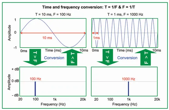
FIGURE 1.1 Relationship of time and frequency
1.1.5 Amplitude (magnitude)
Amplitude is the quantitative measure of oscillating energy, the extent of mechanical displacement (m, cm, etc.), acoustical pressure change (SPL), electrical voltage change (V), magnetic flux (B) and others. Amplitude values can be expressed linearly (e.g. volts) or logarithmically as a ratio (the dB scale). Amplitude is one of the more straightforward aspects of audio: bigger is bigger. Amplitude (black T-shirt) and magnitude (lab coat) are interchangeable terms. We will introduce audio amplitude in various forms next and then cover the scaling details (such as the dB scale) in section 1.2. It may be necessary to bounce between those sections if you are completely unfamiliar with these scales.
1.1.5.1 DC Polarity (Absolute Polarity)
DC (direct current) polarity is the signal’s directional component (positive or negative) relative to equilibrium. Electrical: +/- voltage, acoustical +/- pressure (pressurization/rarefaction), etc. This is applicable in strict terms to DC signals only, because AC signals have both positive and negative values. A 9 V battery illustrates the electrical version. Connecting the battery to a speaker illustrates the acoustical version, because it only moves in one direction.
1.1.5.2 Absolute Amplitude
Absolute amplitude is the energy level relative to equilibrium (audio silence). Electrical audio silence is 0 VAC, whether DC is present or not. Only AC can make audio. DC moves a speaker but unfortunately the only sound it can make is the speaker burning. Acoustic systems are referenced to changes above or below the ambient air pressure (air’s equivalent for DC). Absolute amplitude values cannot be less than zero, because we can’t have less movement than equilibrium. A “-” sign in front of an amplitude value indicates negative polarity. Relative amplitude values are more common in audio than absolute ones.
1.1.5.3 Relative to a Fixed Reference
Audio levels change on a moment-to-moment basis. Therefore most amplitude measurements are relative to a reference (either fixed or movable). Examples of fixed references include 1 V (electrical) or the threshold of human hearing (acoustical) (Fig. 1.2). The reference level can be expressed in various units and scales, as long as we agree on the value. An amplitude value of 2 volts can be expressed as 1 volt above the 1 V volt reference (linear difference) or twice the reference level (linear multiple). Many reference standards for audio are specified in decibel values (dB), which show amplitude changes in a relative log scale (like our hearing).
One volt, 0 dBV and +2.21 dBu are the same amount of voltage, expressed in different units or scales. A musical passage with varying level over time can be tracked against the fixed reference, e.g. a certain song reaches a maximum level of 8 volts (+18 dBV, +20.21 dBu) and an acoustical level of 114 dB SPL (114 dB above the threshold of hearing).
1.1.5.4 Relative to a Variable Reference (Amplitude Transfer Function)
We can monitor the amplitude of constantly changing signals in second-cousin form, i.e. relative to a relative (Fig. 1.3). We compare signal entering and exiting a device, such as music going through a processor. The relative/ relative measurement (the 2-channel output/input comparison) is termed “transfer function measurement,” the primary form of analysis used in system optimization. Frequency response amplitude traces in this book are relative amplitude (transfer function) unless specified otherwise.
Let’s return to the above example. The music level is changing, but the output and input waveforms track consistently as long as the processor gain remains stable. If output and inputs are level matched (a 1:1 ratio), the device has a transfer function voltage gain of unity (0 dB). If the voltage consistently doubles, its transfer function gain is 2× (+6 dB). We can span the electronic and acoustic domains by comparing the processor output with the sound level in the room. This reveals a voltage/SPL tracking relationship, such as +0 dBV (1 V) creates 96 dB SPL (and +6 dBV (2 V) creates 102 dB SPL etc.).
The beauty of transfer function measurement is its ability to characterize a device (or series of devices) with random input material across multiple media, so long as the waveforms at both ends are correlated. This will be covered extensively in Chapter 12.
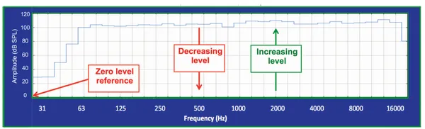
FIGURE 1.2 Absolute amplitude vs. frequency. Amplitude is referenced to 0 dB SPL at the bottom of the vertical scale.
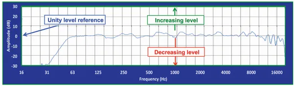
FIGURE 1.3 Transfer function amplitude vs. frequency. Amplitude is referenced to unity gain at the center of the vertical scale.
1.1.5.5 Peak (PK) and Peak-To-Peak (PK-PK)
The peak (pk) amplitude value is the signal’s maximum extent above or below equilibrium whereas peak-to-peak (pk–pk) is the span between above and below values. Any device in the transmission path must be capable of tracking the full extent of the pk–pk amplitude. Failure results in a form of harmonic distortion known as “clipping” (because the tops of the peaks are flattened). The waveform seen on an oscilloscope or digital audio workstation is a representation of the pk–pk values.
1.1.5.6 RMS (Root Mean Squared)
The rms value (root-mean-squared) is the waveform’s “average-ish” amplitude. The rms calculation makes AC (+ and -) equivalent to DC (+ or -). For example a 9 VDC battery and 9 VRMS generator supply the same power. We use rms instead of simple averaging because audio signals move bo...