This introduction to descriptive geometry and contemporary drafting guides the student through the essential principles to create engineering drawings that comply with international standards of technical product specification. This heavily updated new edition now applies to CAD as well as conventional drawing. Extensive new coverage is given of:
• International drafting conventions
• Methods of spatial visualisation such as multi-view projection
• Types of views
• Dimensioning
• Dimensional and geometric tolerancing
• Representation of workpiece and machine elements
• Assembly drawings
Comprehensible illustrations and clear explanations help the reader master drafting and layout concepts for creating professional engineering drawings. The book provides a large number of exercises for each main topic. This edition covers updated material and reflects the latest ISO standards.
It is ideal for undergraduates in engineering or product design, students of vocational courses in engineering communication and technology students covering the transition of product specification from design to production.
Domande frequenti
Come faccio ad annullare l'abbonamento?
È semplicissimo: basta accedere alla sezione Account nelle Impostazioni e cliccare su "Annulla abbonamento". Dopo la cancellazione, l'abbonamento rimarrà attivo per il periodo rimanente già pagato. Per maggiori informazioni, clicca qui
È possibile scaricare libri? Se sì, come?
Al momento è possibile scaricare tramite l'app tutti i nostri libri ePub mobile-friendly. Anche la maggior parte dei nostri PDF è scaricabile e stiamo lavorando per rendere disponibile quanto prima il download di tutti gli altri file. Per maggiori informazioni, clicca qui
Che differenza c'è tra i piani?
Entrambi i piani ti danno accesso illimitato alla libreria e a tutte le funzionalità di Perlego. Le uniche differenze sono il prezzo e il periodo di abbonamento: con il piano annuale risparmierai circa il 30% rispetto a 12 rate con quello mensile.
Cos'è Perlego?
Perlego è un servizio di abbonamento a testi accademici, che ti permette di accedere a un'intera libreria online a un prezzo inferiore rispetto a quello che pagheresti per acquistare un singolo libro al mese. Con oltre 1 milione di testi suddivisi in più di 1.000 categorie, troverai sicuramente ciò che fa per te! Per maggiori informazioni, clicca qui.
Perlego supporta la sintesi vocale?
Cerca l'icona Sintesi vocale nel prossimo libro che leggerai per verificare se è possibile riprodurre l'audio. Questo strumento permette di leggere il testo a voce alta, evidenziandolo man mano che la lettura procede. Puoi aumentare o diminuire la velocità della sintesi vocale, oppure sospendere la riproduzione. Per maggiori informazioni, clicca qui.
Geometric and Engineering Drawing è disponibile online in formato PDF/ePub?
Sì, puoi accedere a Geometric and Engineering Drawing di Ken Morling, Stéphane Danjou in formato PDF e/o ePub, così come ad altri libri molto apprezzati nelle sezioni relative a Tecnologia e ingegneria e Ricerca e competenze ingegneristiche e tecnologiche. Scopri oltre 1 milione di libri disponibili nel nostro catalogo.
Chapter 1Introduction to Engineering Communication
DOI: 10.1201/9781003001386-1
1.1 PRODUCT DEVELOPMENT AND THE ENGINEERING DESIGN PROCESS
There are many different definitions for the engineering design process. However, they all share common attributes. In the broad view, engineering design, sometimes also referred to as technical design, is a systematic process where basic sciences such as mathematics and physics as well as engineering sciences are applied to solve a given problem. So it is about devising a component or a system while taking predetermined requirements into account to meet the desired needs.
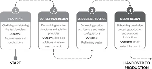
Usually, engineering design follows a well-defined sequence of process steps. From a macroscopic perspective, the engineering design process can be broken down into four stages (see Figure 1.1).
At the very beginning, a design engineer is confronted with a problem statement. Note that a technical problem is given when the solution is not available with the help of already known means. As a result, it is the task of an engineer to establish a clear task description by clarifying the frame conditions and specifying the requirements. The latter can result from customer requirements such as performance, ergonomic or aesthetic requirements, from internal requirements such as considerations with respect to manufacturing or costs, or from external requirements like social and regulatory issues. The complete set of requirements represents constraints the developed technical solution will need to satisfy.
In a second step, the challenge is to develop one or more concepts that have the potential to solve the given problem. This is usually done by establishing a desired function structure and searching for working principles that fulfil the subfunctions. When combining the found working principles into so-called working structures while taking technical and economic constraints into consideration, we will get a set of principle solution variants.
Once principle solutions have been found that meet given evaluation criteria, the design process steps forward into an embodiment design phase where key modules are defined. At this stage, the size of product features or assembly components as well as their arrangement are determined. The outcome of the embodiment design are detailed layouts with respect to main function carriers and auxiliary function carriers. In addition to the basic rules of embodiment design ‘clarity’, ‘simplicity’, ‘sustainability’ and ‘safety’, numerous so-called principles of embodiment design and guidelines, depending on the selected manufacturing process, have to be taken into account. Further, the design is checked against errors, any kind of disturbing factors and possible risks.
Figure 1.1 The engineering design process.
A subsequent detail design process step, where all design details are finalised and where compliance with initial requirements are checked with the help of prototypes and tests, results into a set of product documents, partly needed for production and operation. This can include:
Manufacturing drawings
Assembly drawings
Bill of materials (BOM), also known as parts lists
Production/assembly/transportation instructions
User manual
Manual for maintenance
Spare parts lists
All documents are then checked with regard to completeness, correctness and standards they need to comply with.
It can be seen that in the course of the engineering design process it is essential to communicate to others first ideas, concepts and preliminary design modules as well as the final design. The modern world of engineering is not a one-person show. Instead, it is the result of interdisciplinary teamwork. Therefore, providing a clear picture of such a technical idea and conveying it to various people, inside or outside an organisation, is of high importance and requires an effective and efficient mode of communication.
1.2 COMMUNICATION MODES
Since the beginning of humankind, people have developed several modes of communication. One of the first communication modes was sound. A variety of sounds had different meanings, such as warning others from an existing threat. As a drawback, sounds could be interpreted in different ways, if not commonly agreed on in a group. In addition, communication with the help of sound was limited to basic information.
As civilisation improved, humans used signs for communication. This could have been a fire signal, a pattern of stones, or symbols such as the ancient Sumerian cuneiform and the Egyptian hieroglyphics which were developed in 3500–3000 BC. With the development of alphabets, the written language became a versatile and sophisticated mode of communication.
In the same period, humans started to express themselves with the help of more complex sketches and pictures. Graphics language was born. Over the millennia, graphic representations became a basic and natural form of communication, regardless of the spoken language.
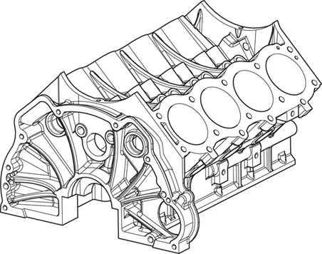
In the engineering field, the effectiveness of graphics language can be easily seen when trying to fully describe an object verbally or in writing. While this might be possible for simple objects, a precise verbal or written description without ambiguity of a more complex object seems to be impossible. As an example, see Figure 1.2 which shows a V8 engine block.
Figure 1.2 V8 engine block.
Graphic representations can be divided into artistic drawings, technical drawings and (technical) illustrations. Drawings from artists are a form of graphic expression of feelings or an idea and have appreciation as their focus. The purpose of an artistic drawing frequently is aesthetic. This kind of drawing is usually subjectively interpreted. In contrast, technical drawings have the purpose of conveying clear information about an object or system, especially how it is constructed or how it functions. As a result, technical drawings are not subject to interpretation but have an intended meaning with no room for misinterpretation.
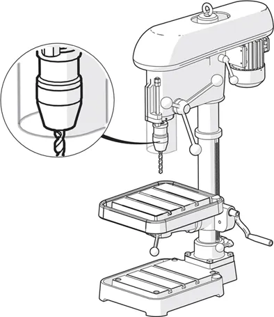
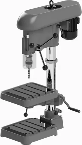
While drawings and illustrations are both visual representations to convey a particular message by its creator, an illustration is neither purely artistic nor purely technical. Instead, an illustration usually supports the understanding of an accompanying textual content. Within the engineer’s world, this kind of graphic representation typically can be found in product documentation such as user manuals, operator manuals or maintenance manuals, for example for machines, automobiles or consumer products. As an example, Figure 1.3 shows a technical illustration of a pillar drill.
Figure 1.3 Technical illustration of a pillar drill.
Technical illustrations enable us to transfer product-related information or to convey complex matters. When communicating with the general public, this type of graphic representation can enhance the interest and understanding of a non-technical audience. Simplification of a product or assembly usually helps to draw attention to the area, feature or component of interest. For that reason, the illustration should resemble the product in question as much as possible but should also omit details which do not contribute to understanding.
The reason that illustrations are so much better than a mere verbal description is that text always needs to be processed in a sequential manner. Illustrations can be analysed within an instant and need no translation. In the end, the saying ‘A picture is worth a thousand words’ also applies to technical applications.
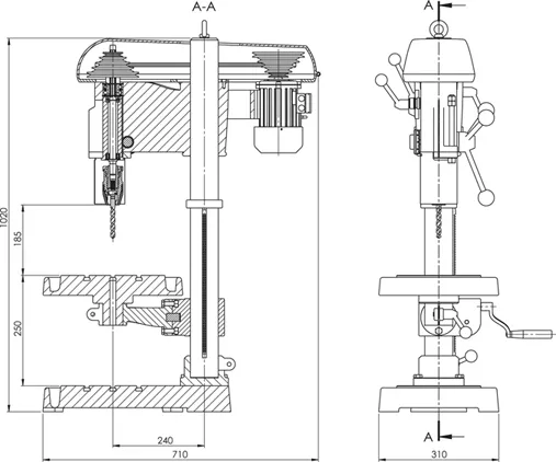
While technical illustrations can be the optimum communication mode for certain applications, in some cases a pure graphical representation is not precise enough and needs additional information, especially when it comes to communication on a more scientific level or between experts in the engineering field. So the graphic representation would need to be enriched by specialised technical terminology and symbols. This brings us to technical drawings. In contrast to artistic drawings and technical illustrations, this kind of graphic representation is a detailed and precise document that conveys information about how an object is designed and functions, and how it is supposed to be manufactured and assembled. The drawing is the road map which shows how a product functions, how it had been designed or how it is going to be manufactured. To guarantee that a technical drawing can be understood by any engineer, no matter of which origin or educational background, the elements of the graphic representation follow a set of international standards. By applying internationally developed and approved regulations to standardise the language used, ambiguous interpretation can be avoided. Figure 1.4 depicts a technical drawing of the previous example of a pillar drill. When comparing Figure 1.3 and Figure 1.4, one can realise that comprehension of the overall geometry and identification of individual components is much easier in the technical illustration. The technical drawing provides more information, such as the overall dimensions and the geometric relationships between the components due to the sectional view, which also enables identification of internal parts.
Nowadays, technical drawings are created with the help of computer-aided design (CAD) software packages. In the 1970s and 1980s, the main purpose of using a 2D CAD system was to create a technical drawing. With the introduction of 3D CAD systems in the late 1980s and early 1990s, the desired end product became a virtual three-dimensional model which contains a description of the geometry and serves as a common basis for downstream processes such as simulation, analysis and machining. While manual drafting required a large workspace, specific drafting equipment, and a lot of time to create and edit a drawing, computer-based drafting allows accurate and reproducible engineering drawings in a shorter time, since they can be automatically derived from the driving 3D model. As already mentioned, creating a technical drawing nowadays is not the sole advantage of such CAD systems. Further development of the functionality and increasing computing power led to expert systems for conceptualisation and the design of technical solutions. Regarding communication, 3D CAD systems meanwhile offer various possibilities to represent an object as realistically and as precisely as possible. Figure 1.5 demonstrates how realistic the pillar drill from previous paragraphs can look when a rendered model is created with the help of a modern CAD system.
Figure 1.4 Technical drawing of a pillar drill.
If CAD systems can provide such impressive photo-realistic images of an object, why do we need (manual) drafting then? It seems that drafting skills are obsolete and that the necessary messages in an engineering design process can be transported via virtual models which show all the characteristics of an object to a very high level of detail.
1.3 IMPORTANCE OF ENGINEERING DRAWING
Engineering drawings still play a major role in the engineering design process since they can be easily understood, once the drafting conventions are known. They can also provide a lot of information regarding a technical solution, beyond the apparently visible. Accompanied by standardised ideograms or annotations, engineering drawings become the ideal mode of communication to convey information between the various parties involved in the design process and even the product development process. Owing to their versatile possible use, engineering drawings serve at minimum one of three purposes, frequently all of them at the same time: