![]()
CHAPTER I
PRECISION LOCATING AND DIVIDING METHODS
The degree of accuracy that is necessary in the construction of certain classes of machinery and tools, has made it necessary for toolmakers and machinists to employ various methods and appliances for locating holes or finished surfaces to given dimensions and within the prescribed limits of accuracy. In this chapter, various approved methods of locating work, such as are used more particularly in tool-rooms, are described and illustrated.
Button Method of Accurately Locating Work. — Among the different methods employed by toolmakers for accurately locating work such as jigs, etc., on the faceplate of a lathe, one of the most commonly used is known as the “button method.” This method is so named because cylindrical bushings or buttons are attached to the work in positions corresponding to the holes to be bored, after which they are used in locating the work. These buttons which are ordinarily about
or
inch in diameter, are ground and lapped to the same size, and the ends are finished perfectly square. The outside diameter should preferably be such that the radius can easily be determined, and the hole through the center should be about
inch larger than the retaining screw so that the button can be adjusted laterally.
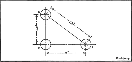
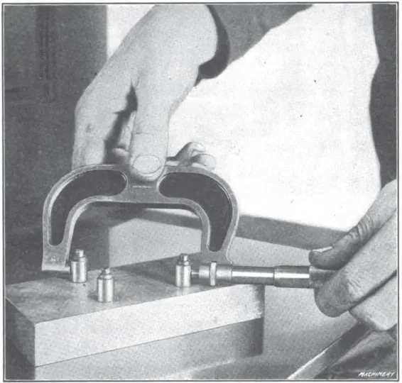
As a simple example of the practical application of the button method, suppose three holes are to be bored in a jig-plate according to the dimensions given in Fig. 1. A common method of procedure would be as follows: First lay out the centers of all holes to be bored, by the usual method. Mark these centers with a prick-punch and then drill holes for the machine screws which are used to clamp the buttons. After the buttons are clamped lightly in place, set them in correct relation with each other and with the jig-plate. The proper location of the buttons is very important, as their positions largely determine the accuracy of the work. The best method of locating a number of buttons depends somewhat upon their relative positions, the instruments available, and the accuracy required. When buttons must be located at given distances from the finished sides of a jig, a surface plate and vernier height-gage are often used. The method is to place that side from which the button is to be set, upon an accurate surface plate and then set the button by means of the height-gage, allowance being made, of course, for the radius of the button. The center-to-center distance between the different buttons can afterwards be verified by taking direct measurements with a micrometer (as indicated in Fig. 2) by measuring the overall distance and deducting the diameter of one button.
Fig. 1. Simple Example of Work Illustrating Application of Button Method
After the buttons have been set and the screws are tightened, all measurements should be carefully checked. The work is then mounted on the faceplate of the lathe and one of the buttons is set true by the use of a test indicator. When the dial of the indicator ceases to vibrate, thus showing that the button runs true, the latter should be removed so that the hole can be drilled and bored to the required size. In a similar manner other buttons are indicated and the holes bored, one at a time. It is evident that if each button is correctly located and set perfectly true in the lathe, the various holes will be located the required distance apart within very close limits.
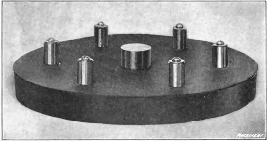
Another example of work illustrating the application of the button method is shown in
Fig. 3. The disk-shaped part illustrated is a flange templet which formed a part of a fixture for drilling holes in flanged plates, the holes being located on a circle 6 inches in diameter. It was necessary to space the six holes equi-distantly so that the holes in the flanges would match in any position, thus making them interchangeable. First a plug was turned so that it fitted snugly in the
-inch central hole of the plate and projected above the top surface about
inch. A center was located in this plug and from it a circle
of three inches radius was drawn. This circle was divided into six equal parts and then small circles
inch in diameter were drawn to indicate the outside circumference of the bushings to be placed in the holes. These circles served as a guide when setting the button and enabled the work to be done much more quickly. The centers of the holes were next carefully prick-punched and small holes were drilled and tapped for No. 10 machine screws. After this the six buttons were attached in approximately the correct positions and the screws tightened enough to hold the buttons firmly, but allow them to be moved by tapping lightly. As the radius of the circle is 3 inches, the radius of the central plug,
inch, and that of each button,
inch, the distance from the outside of the central plug to the outside of any button, when correctly set, must be
inches. Since there are six buttons around the circle, the center-to-center distance is equal to the radius, and the distance between the outside or any two buttons should be
inches. Having determined these dimensions, each button is set equi-distant from the central plug and the required distance apart, by using a micrometer. As each button is brought into its correct position, it should be tightened down a little so that it will be located firmly when finally set. The work is then strapped to the faceplate of a lathe and each button is indicated for boring the different holes by means of an indicator, as previously described.
When the buttons are removed it will be found that in nearly all cases the small screw holes will not run exactly true; therefore it is advisable to form a true starting point for the drill by using a lathe tool.
Fig. 2. Testing Location of Buttons
Fig. 3. Flange Templet with Buttons Attached
When doing precision work of this kind, the degree of accuracy obtained will depend upon the instruments used, the judgment and skill of the workman, and the care exercised. A good general rule to follow when locating bushings or buttons is to use the method which is the most direct and which requires the least number of measurements, in order to prevent an accumulation of errors.
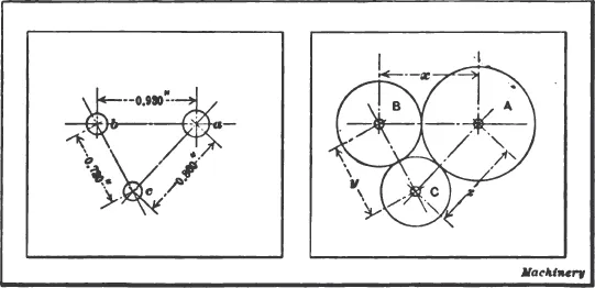
Locating Work by the Disk Method. — Comparatively small precision work is sometimes located by the disk method, which is the same in principle as the button method, the chief difference being that disks are used instead of buttons. These disks are made to such diameters that when their peripheries are in contact, each disk center will coincide with the position of the hole to be bored; the centers are then used for locating the work. To illustrate this method, suppose that the master-plate shown at the left in Fig. 4 is to have three holes a, b and c bored into it, to the center distances given.
It is first necessary to determine the diameters of the disks. If the center distances between all the holes were equal, the diameters would, of course, equal this dimension. When, however, the distances between the centers are unequal, the diameters may be found as follows: Subtract, say, dimension y from x, thus obtaining the difference between the radii of disks C and A (see right-hand sketch); add this difference to dimension z, and the result will be the diameter of disk A. Dividing this diameter by 2 gives the radius, which, subtracted from center distance x equals the radius of B; similarly, the radius of B subtracted from dimension y equals the radius of C.
For example, 0.930 − 0.720 = 0.210 or the difference between the radii of disks
C and
A. Then the diameter of
A = 0.210 + 0.860 = 1.070 inch, and the radius equals 1.070
2 = 0.535 inch. The radius of
B = 0.930 − 0.535 = 0.395 inch and 0.395 × 2 = 0.790, or the diameter of
B. The center distance
0.720 − 0.395 = 0.325, which is the radius of
C; 0.325 × 2 = 0.650 or the diameter of
C.
After determining the diameters, the disks should be turned nearly to size and finished, preferably in a bench lathe. First insert a solder chuck in the spindle, face it perfectly true, and attach the disk by a few drops of solder, being careful to hold the work firmly against the chuck while soldering. Face the outer side and cut a sharp V-center in it; then grind the periphery to the required diameter. Next fasten the finished disks onto the work in their correct locations with their peripheries in contact, and then set one of the disks exactly central with the lathe spindle by applying a test indicator to the center in the disk. After removing the disk and boring the hole, the work is located for boring the other holes in the same manner.
Fig. 4. An Example of Precision Work, and Method of Locating Holes by Use of Disks in Contact
Small disks may be secured to the work by means of jeweler’s wax. This is composed of common rosin and plaster of Paris and is made as follows: Heat the rosin in a vessel until it flows freely, and then add plaster of Paris and keep stirring the mixture. Care should be taken not to make the mixture too stiff. When it appears to have the proper consistency, pour some of it onto a slate or marble slab and allow it to cool; then insert the point of a knife under the flattened cake thus formed and try to pry it off. If it springs off with a slight metallic ring, the proportions are right, but if it is gummy and ductile, there is too much rosin. On the other hand, if it is too brittle and crumbles, this indicates that there is too much plaster of Paris. The wax should be warmed before using. A mixture of beeswax and shellac, or beeswax and rosin in about equal proportions, is also used for holding disks in place. When the latter are fairly large, it may be advisable to secure them with small screws, provided the screw holes are not objectionable.
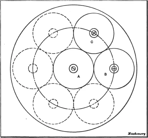
Disk-and-button Method of Locating Holes. — The accuracy of work done by the button method previously described is limited only by the skill and painstaking care of the workman, but setting the buttons requires a great deal of time. By a little modification, using what is sometimes called the “disk-and-button method,” a large part of this time can be saved without any sacrifice of accuracy. The disk-and-button method, which was described by Guy H. Gardner in MACHINERY, September, 1914, is extensively used in many shops. Buttons are used, but they are located in the centers of disks of whatever diameters are necessary to give the required locations. As three disks are used in each step of the process, it is sometimes called the “three-disk method.”
Fig. 5. Locating Equi-distant Holes on a Circle by Using Disks and Buttons in Combination
To illustrate the practical application of this method, suppose six equally-spaced holes are to be located in the circumference of a circle six inches in diameter. To locate these, one needs, besides the buttons, three disks three inches in diameter, each having a central hole exactly fitting the buttons. It is best to have, also, a bushing of the same diameter as the buttons, which has a center-punch fitted to slide in it. First, the center button is screwed to the templet, and one of the disks A, Fig. 5, is slipped over it; then a second disk B carrying a bushing and center-punch is placed in contact with disk A and a light blow on the punch marks the place to drill and tap for No. 2 button, which is kept in its proper place while tightening the screw by holding the two disks A and B in contact. Next, the third disk ...