![]()
Chapter 1
Introduction
Antennas have been around now for nearly 125 years. In those 125 years wireless communication has become increasingly important. Personal mobile communication applications are putting huge constraints on the antennas that need to be housed in limited spaces. Therefore the common practice of wireless engineers to consider the antenna as a black-box component is not valid anymore. The modern wireless engineer needs to have a basic understanding of antenna theory. Before we dive into the derivation of antenna characteristics, however, we will—in this chapter—present a brief overview of antenna history and the mechanisms of radiation. Thus, a solid foundation will be presented for understanding antenna characteristics and their derivations.
1.1 The Early History of Antennas
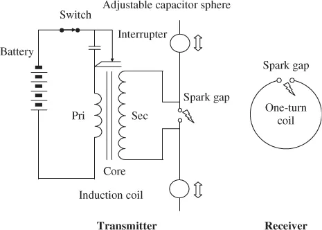
When James Clerk Maxwell, in the 1860s, united electricity and magnetism into electromagnetism, he described light as—and proved it to be—an electromagnetic phenomenon. He predicted the existence of electromagnetic waves at radio frequencies, that is at much lower frequencies than light. In 1886, Maxwell was proven right by Heinrich Rudolf Hertz who—without realizing it himself1—created the first ever radio system, consisting of a transmitter and a receiver, see Figure 1.1.
The transmitting antenna, connected to a spark gap at the secondary windings of a conduction coil, was a dipole antenna. The receiving antenna was a loop antenna ending in a second spark gap. Hertz, who conducted his experiments at frequencies around 50 MHz, was able to create electromagnetic waves and to transmit and receive these waves by using antennas. This immediately raises two questions:
1. What is an antenna?
2. How is electromagnetic radiation created?
1.2 Antennas and Electromagnetic Radiation
From the previous it is obvious that
An antenna is a device for transmitting or receiving electromagnetic waves. An antenna converts electrical currents into electromagnetic waves (transmitting antenna) and vice versa (receiving antenna).
Before we describe this in detail, we will first take a closer look at the origin of electromagnetic radiation.
1.2.1 Electromagnetic Radiation
The source of electromagnetic radiation is accelerated (or decelerated) charge.
Let's start with a static, charged object and have a look at the electric field lines. These lines are the trajectories of a positively charged particle due to this static, charged object. Electric field lines are always directed perpendicular to the surface of a charged object and start and end on charged objects. Electric field lines due to single charged objects start at or extend towards infinity. For a positively charged object, the electric field lines start at the object and extend towards infinity, for a negatively charged object they start at infinity and end at the object.
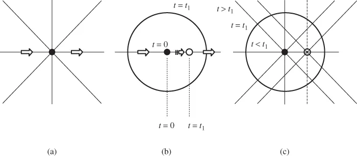
For explaining the mechanisms of radiation, the direction of the electric field lines does not matter, therefore in Figure 1.2(a), where we show a uniformly moving particle at a certain instant of time, we do not indicate the direction of the field lines.
The uniformly charged particle is accelerated between t = 0 and t = t1, see Figure 1.2(b), after which it continues its uniform movement. In Figure 1.2(b) we have indicated the position of the particle at the start (t = 0) and at the end (t = t1) of the acceleration. Also indicated is the position of an observer that has moved with the speed of light along a static electric field line from the particle, for the duration of the acceleration (t1).
In Figure 1.2(c) we repeat Figure 1.2(b), where we now also indicate static electric field lines associated with the particle at t = 0 and at t = t1.
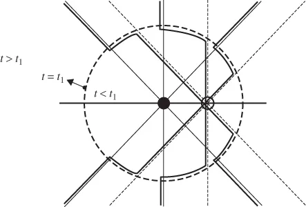
We now think of ourselves positioned anywhere on the ‘observer circle’ and accept that nothing can move faster than the speed of light. Then, everywhere from the ‘observer circle’ to infinity, the static field lines must follow those associated with the particle position at t = 0. Everywhere inside the circle, the static field lines must follow those associated with the particle position at t = t1. Since electric field lines must be continuous, so-called kinks must exist at the observer position to make the electric field lines connect, see Figure 1.3.2
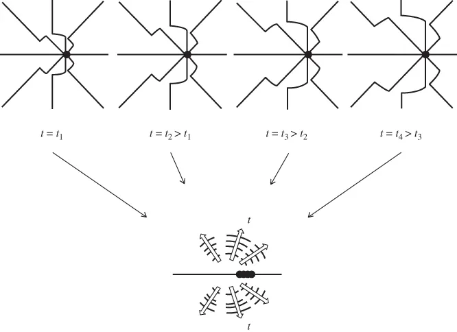
Having explained the construction of electric field lines for an accelerated charged particle, we can now take a closer look at the electric field lines as a function of time. In Figure 1.4 we look at the electric field lines at different times within the acceleration time interval.
When we take the disturbances, that is the transverse components of the electric field, taken at the subsequent moments and add them in one graph, as in Figure 1.4, we see that these disturbances move out from the accelerated charge at the speed of light. Associated with the changing electric field is a changing magnetic field. Both fields are in phase3 since they are due to a single event. The electric and magnetic fields travel along in phase, their directions being perpendicular to each other. This is what we call an electromagnetic wave.
Accelerating (or decelerating) charges may be found in electrically conducting wires at positions were the wire is bent, curved, discontinuous or terminated. Before we discuss the radiation from a wire dipole antenna in detail, we note that, see Figure 1.4, radiation does not take place in directions along the charged particle acceleration.
Next, we will take a look at the radiation from a short dipole antenna.
1.2.2 Short Wire Dipole Radiation
We consider two short—that is much shorter than a wavelength—electrically conducting wires, each folded back 90 degrees, and connected to an AC source. We will look at the electric field around this structure at different instances of time within one half of the period T, see Figure 1.5.
- t = 0+, see Figure 1.5(a). The time is a short while after t = 0. The source has been turned on and charge is accelerated from the source to the wire ends. Because of the acc...