![]()
Chapter 1
Transformation of Flow Power
The systems transforming the energy of wind currents can be either those employing mechanical action in combination with electric, pump, frictional or thermal units, or those employing non-mechanical action, using, for example, an effect of ionization and conductivity of the stream passed through an electric or magnetic field. All mechanical systems, called - power installations (PI), use the action of the forces arising at a flow of mobile elements of the installations which are structurally united into power rotors (PR). The PI’s working elements, PR, move on the closed routes, sweeping some surfaces where the axis of symmetry can be either parallel (collinear), or perpendicular (orthogonal) to the stream. Respectively, PR are classified into two groups:
- Collinear, at which the axis of symmetry is approximately parallel to the stream, and
- Orthogonal, at which the axis of symmetry lies in the orthogonal plane to the stream direction.
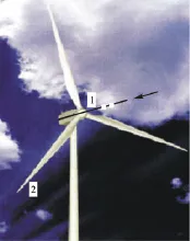
The PR elements are able to move more slowly or quickly than the stream on the way to the PR. Respectively, they are called low-speed (action turbine) or high-speed (reaction turbine) machines. The collinear high-speed units (see Figure 1.1) are the most popular at present. Other types of units are not even included in the modern handbooks [1].
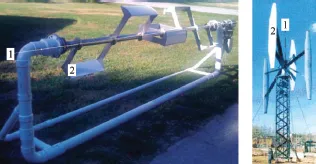
The orthogonal units may have a horizontal or a vertical axis (see Figure 1.2).
Comparing various types of power installations of even one class causes certain difficulties as it is necessary to take into account some criteria measured in different equipment: specific material consumption (per a power unit and an output), quality of developed energy degree of simplicity and factory readiness, convenience and reliability in operation, labor input of construction and operation, ecological safety. The combination of these criteria defines the multidimensional quality characteristics of PR. Comparing PR quality is especially difficult for machines of various classes. Therefore, the choice of perspective schemes is conditional. The cost change (the social importance) of some points in view of the quality may change the conclusions. However, the economic, power, and ecological indicators currently accepted as the main points, should preserve the value for many years.
Since the wave aerodynamic resistance and acoustic radiation greatly increases when the body movement speeds approach the speed of sound, the wind unit elements should be designed so that air flows around them at speeds significantly less than sound speed (with small Mach numbers). Thus, the air can be considered almost incompressible, or squeezed under any law (adiabatically or isothermally); and all the results of aerodynamic calculations become suitable for recalculation by the movement conditions of incompressible liquids with any other density. In particular, all results can be directly applied to the analysis of river or oceanic power installations of similar configurations. Thus, one should keep in mind that for quiet water streams with small Froude numbers, the role of the stream free surface is somewhat close to the role of a firm smooth wall. [2]
Therefore, the analogy, for example, between land wind and river (oceanic) installations can be twofold – applying both to the arrangement of units at the water surface or at the bottom of a reservoir. Certainly, the designs of the units, applied materials, strength and technical and economic estimates for power units can vary significantly in air and in water.
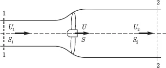
In any scheme of stream power selection it makes sense to replace, as the first approximation, the unit which is carrying out this process with some hypothetical flat permeable figure with contours which are projections of the borders of a body, swept around by the rotor, on the figure plane, perpendicular to the stream direction on the way to the unit (Figure 1.3).
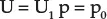
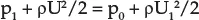
In the case of traditional, collinear units, a circle or a ring will be such a figure; in the case of orthogonal units it can be a strip (as in the pictured model), a rectangle, a trapeze, an ellipse figure (Darrieus unit section) or a triangle. Whatever this figure is, at some distance in front of it, the stream speed U and pressure p keep an non-indignant value:
and at some distance downstream, where the pressure distribution across the stream is leveled and returns to a reference value p0, the speed in the current tube leaning on the allocated figure has a smaller value U2 = (U1 - u). If the current speed through the allocated figure is designated as U, and the pressure from the frontal and back parts of the figure as p1 and p2, respectively, the Bernoulli equations for the front and back parts of the current tube will take the following form:
If the stream speed and the surface pressure upon of the allocated current tube are accepted as constant, the equation of change of the movement quantity for the allocated volume is:
- Discharge of the medium moving in the considered current tube, S - the surface area imitating a turbine,
- Difference of pressure on the allocated flat figure replacing the power unit is calculated by subtraction of equalities (3) from equality (2) taking into account (4) and (5):
From the equations (2)-(5), we find:
The capacity lost by the stream and transferred to the turbine, is equal to:
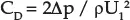
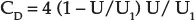
The found solution (6), (8), presented as a resistance coefficient:
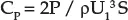
and a power factor:
appears depending on one parameter only - the relative stream speed in the unit zone U/U1.
The maximum value of power observed at U/U1 = u/U1 =2/3 makes:
The obtained ratios (6), (8), (13) are usually associated with the works of N.E. Zhukovsky (1912) and A. Betz (1919), giving a sense of certain limit laws to these ratios [4].
However, the reality is different. The initial equations (2) – (5) are not precise and reflect some model of the phenomenon only. In particular, the equation (3) obviously is not true at U→0. If this limit case is real (an impenetrable unit), the pressure p2 behind the unit will obviously be less than the pressure p0 at a distance from the unit, rather than greater, as follows from (3). However, the idea of replacing the unit with one or several permeable flat or other figures where a rupture of ...