![]()
1
Introduction to AC Motor Control
Marc Bodson1 and Fouad Giri2
1Electrical and Computer Engineering, University of Utah, USA
2GREYC Lab, University of Caen Basse-Normandie, France
1.1 AC Motor Features
The principles of operation of (AC) motors may be found in many books, including Hindmarsh (1985), Vas (1990), Leonard (2001) and Chiasson (2005). In this section, some basic facts are recalled, focusing on the features that contribute to the success of AC motors in motion control and to the continuing growth of their applications. “AC motors” refers to electric machines that convert AC electric energy into mechanical energy. There is a wide variety of such machines that differ by their operating principles, physical characteristics, and power level. Considering their operating principles, AC motors are classified in two main categories: induction and synchronous.
Induction motors exist in two main types, squirrel cage and wound rotor. In wound rotor machines, both the stator and the rotor windings are made of individually insulated coils. The rotor coils are made accessible on the stator side through slip rings. In squirrel-cage machines, the rotor windings are replaced by longitudinal bars placed in slots beneath the rotor’s outer surface. The rotor bars are connected by circular conductors placed at the extremities. Operationally, a squirrel-cage motor is similar to a wound rotor motor with short-circuited windings.
For both types of motors, the stator windings generate a rotating magnetic field when supplied with polyphase AC. The speed of rotation of the field is given by the stator current frequency divided by the number of magnetic pole pairs created by the windings. By Faraday’s and Lenz’s laws, currents are induced in the rotor windings whenever the rotor speed differs from the speed of the magnetic field produced by the stator. This speed difference, called slip speed, must be kept small to guarantee high-energy conversion efficiency. Under this constraint, a change of rotational speed requires an adjustment of the stator electrical frequency.
Synchronous motors also exist in two versions, namely, permanent-magnet and wound rotor. Unlike induction motors, there are no induced rotor currents in synchronous motors in steady state, because the rotor rotates at the same speed as the rotating magnetic field. A motor torque is developed due to the interaction between the stator rotating field and a rotor field generated either by permanent magnets or by an injected rotor current.
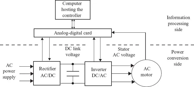
For both induction and synchronous motors, variable speed operation is possible if the stator supply frequency is made variable. Until the development of modern power electronics, there was no simple and effective way to vary the frequency of the motors’ supply voltages. Nowadays, reliable high-speed switching power converters are available that serve as actuators in AC motor control. Specifically, an AC motor is supplied with power through an association of two power converters, a rectifier and an inverter (Figure 1.1). The former, also called AC/DC converter, converts the AC power provided by the grid into DC power. Control of the rectifier is not always implemented, but is useful to regulate the DC voltage, or to enable regeneration of power to the grid. The inverter, also referred to as DC/AC converter, transforms the DC voltage into an AC voltage with a specified frequency. The result is achieved by chopping the DC voltage at a high rate, typically using a pulse-width modulation (PWM) technique. In this respect, it is worth emphasizing the considerable progress made in computer technology, which has resulted in fast multiprocessor computers and high-performance analog-digital interfaces. This progress has made possible the real-time implementation of sophisticated methods to control the power converters associated with AC machines.
DC motors require schemes similar to Figure 1.1, but with lower bandwidth requirements and fewer channels. However, ACs are produced in conductors through mechanical commutation, rather than electrical commutation. The commutators of DC motors are complex and vulnerable. As a result, AC motors offer a higher power/mass ratio, relatively low cost, and simple maintenance. AC motors exist with a variety of characteristics and in a large range of sizes, from a few watts to many thousands of kilowatts. For these reasons, AC drive systems have already replaced DC drives in several industrial fields and this widespread proliferation is expected to continue. Nowadays, AC drives are used in almost all industrial applications, such as the following:
1. Transport: vehicle traction, marine propulsion
2. Milling in cement, steel, paper, and others industries
3. Pumping/compressing in oil and gas industry
4. Cranes and industrial vehicles
5. Domestic machines: lifts, washing machines, and others.
1.2 Control Issues
1.2.1 State-Feedback Speed Control
The prime objective in AC motor control is to make the rotor turn at a desired speed despite load variations. If the desired speed is constant, one talks of speed regulation, while tracking problems correspond to time-varying speeds. The desired speed, also called the speed reference signal, is often unknown a priori, making the control issue more difficult. Indeed, the achievement of a desired rotor speed profile necessitates a sufficient motor torque to overcome the load torque, but also to provide the required accelerations of the rotor during transient periods.
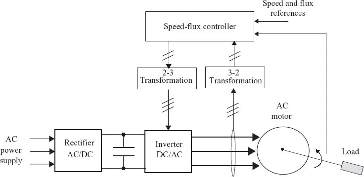
In AC induction motors, the generation of a given torque necessitates a sufficient level of rotor magnetization, that is, a sufficiently high flux magnitude in the rotor. Flux control is thus not independent from the problem of speed control and both are acted upon through the inverter control signals. These signals are binary signals commanding on and off conduction modes. The electromechanical nature of the motor entails nonlinearities associated with products of fluxes with currents and fluxes with speed. Furthermore, the three-phase nature of the motor means that the overall model is nonlinear, of high dimension, as well as controlled through binary signals. A common practice consists in reducing the model dimension by resorting to Park’s transformation, which projects the three-phase variables (generally referred to as abc) on a two-phase rotating coordinate frame (generally referred to as dq) (see, e.g., Blaschke 1972; Leonard 2001). The binary nature of the inverter signals is generally coped with by averaging the signals over the PWM period and letting the control design be based on the corresponding averaged two-coordinate model (see, e.g., Sira-Ramirez and Silva-Ortigoza 2006). Model nonlinearity is handled using modern nonlinear control design techniques, including state- and output-feedback linearization, Lyapunov control, sliding-mode (SM) control, passivity-based control (Ortega et al. 1998; Isidori 1999; Sastry 1999; Vidyasagar 2002; Khalil 2003).
The basic ideas described so far lead to the control strategy depicted in Figure 1.2.
1.2.2 Adaptive Output-Feedback Speed Control
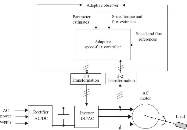
The basic state-feedback control strategy of Figure 1.2 assumes that all controlled system parameters are known. However, some system parameters are generally not known a priori, and may even be varying in normal operating conditions. In particular, the stator and the rotor resistances are sensitive to the magnitude of the currents, and thus undergo wide variations in the presence of speed reference and load torque changes. The rotor-load set inertia and rotor friction coefficient may also vary (e.g., in transportation applications). To maintain the control performance at the desired level despite changing operating conditions, the speed controller may need to be reinforced with a parameter adaptation capability (Krstic, Kanellakopoulos, and Kokotovic 1995; Astolfi, Karagiannis, and Ortega 2007).
Another limitation of the control strategy of Figure 1.2 is that all state variables are assumed to be accessible through measurements. However, reliable and cheap sensors are only available for stator currents and voltages. Flux sensors are generally not available on machines because of their high implementation cost and maintenance complexity. Mechanical sensors (for speed and, more rarely, torque measurements) are common, but also entail reliability issues and extra maintenance costs due to physical contact with rotor. Therefore, state observers are attractive to obtain online estimates of the states based only on electric measurements (Besançon 2007). Sensorless controllers involving online state estimation using observers are commonly referred to as output-feedback controllers. Modern control strategies, illustrated in Figure 1.3, combine both features: parameter adaptation and sensorless output-feedback.
1.2.3 Fault Detection and Isolation, Fault-Tolerant Control
Like any complex system, AC motors are facing faults in otherwise normal operating conditions. Faults may originate from the failure of certain system components, for example, sensors, inverter, rectifier, power supply, or even stator/rotor windings. Sensor failure may result in a loss of observability, while inverter, rectifier, or supply failure may cause a loss of controllability. Regardless, the controller designed on the basis of a faultless model may see its performance deteriorate drastically, sometimes causing unsafe operation of the whole system. To prevent unsafe running and continuously guaranteeing an acceptable level of performances, a fault-tolerant control (FTC) system is needed. The development of FTC systems has been an active research topic, especially over the past 15 years, and a review of relevant concepts and methods can be found in Blanke et al. (2000), Steinberg (2005), and Zhang and Jiang (2008), and Noura et al. (2009). Distinction is usually made between passive and active FTC approaches. In the first case, component failures are considered as disturbances and a single control law is designed so that it is robust against the predefined set of disturbances. The active FTC approaches are those that dynamically react to fault occurrence by performing control reconfiguration. This is mainly done in two ways:
1. Selecting online (within a set of predesigned laws) the control law that best fits the detected fault type.
2. Redesigning online the control law to adapt it to the detected faulty situation.
Active FTC approaches require a fault detection and isolation (FDI) module. The role of the latter is twofold:
1. Making a binary decision, either that something has gone wrong or that everything is fine.
2. Determining the location as well as the na...