![]()
1
Design of Thermo-Fluids Systems
1.1 Engineering Design—Definition
Process of devising a system, subsystem, component, or process to meet desired needs.
1.2 Types of Design in Thermo-Fluid Science
i Process Design: The manipulation of physical and/or chemical processes to meet desired needs.
Example: (a) Introduce boiling or condensation to increase heat transfer rates.
ii System Design: The process of defining the components and their assembly to function to meet a specified requirement.
Examples: (a) Steam turbine power plant system consisting of turbines, pumps, pipes, and heat exchangers.
(b) Hot water heating system, complete with boilers.
iii Subsystem Design: The process of defining and assembling a small group of components to do a specified function.
Example: Pump/piping system of a large power plant. The pump/piping system is a subsystem of the larger power plant system used to transport water to and from the boiler or steam generator.
iv Component Design: Development of a piece of equipment or device.
1.3 Difference between Design and Analysis
| Analysis: |
Application of fundamental principles to a well-defined problem. All supporting information is normally provided, and one closed-ended solution is possible. |
| Design: |
Application of fundamental principles to an undefined, open problem. All supporting information may not be available and assumptions may need to be made. Several alternatives may be possible. No single correct answer exists. |
1.4 Classification of Design
i Modification of an existing device for
a. cost reduction;
b. improved performance and/or efficiency;
c. reduced mean time between “breakdowns”;
d. satisfy government codes and standards;
e. satisfy customer/client preferences.
ii Selection of existing components for the design of a subsystem or a complete system.
iii Creation of a new device or system.
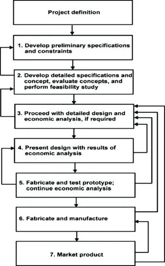
1.5 General Steps in Design
The general steps in the design process are shown schematically in Fig. 1.1.
1.6 Abridged Steps in the Design Process
1. Project Definition: One or two sentences describing the system or component to be designed. Check the problem statement for information.
2. Preliminary Specifications and Constraints: List the requirements that the design should satisfy. Requirements could come from the problem statement provided by the client or from the end users' preferences.
At this point, develop detailed, quantifiable specifications. For example, the client wants a fan-duct system that is quiet. What does “quiet” mean? What are the maximum and minimum noise levels for this “quiet” range? 60 dB may be satisfactory. Could the maximum noise level be 70 dB?
Detailed specifications or requirements could originate from the client (“client desired”), could be internally imposed by the designer to proceed with the design, or could be externally imposed by international/federal/provincial/ municipal/industry standards or codes.
3. Detailed Design and Calculations
i Objective
ii Data Given or Known
iii Assumptions/Limitations/Constraints
iv Sketches (where appropriate)
v Analysis
vi Drawings (where appropriate) or other documentation such as manufacturer's catalog sheets and Specifications.
vii Conclusions
![]()
2
Air Distribution Systems
2.1 Fluid Mechanics—A Brief Review
2.1.1 Internal Flow
Flow is laminar: smooth streamlines; highly ordered motion.
Or
Flow is turbulent: velocity fluctuates with time; highly disordered motion.
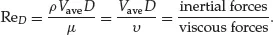
Use the Reynolds number to characterize the flow regime:
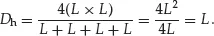
Note: For noncircular pipes or ducts, ReD is based on the hydraulic diameter, Dh:
where Ac is the cross-sectional area and p is the perimeter wetted by the fluid.
For square ducts,
For rectangular ducts,
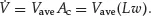
It is important to note that, for volume flow rate calculations, Dh should not be used to find the cross-sectional area. Use the true cross-sectional area.
Therefore, for a rectangular duct,
But
Criteria for Flow Characterization
For engineering design analysis, use a critical Reynolds number, Recr:
2.1.2 Frictional Losses in Internal Flow—Head Losses
For fully developed laminar flow, the volume flow rate is related to the pressure drop via Poiseuille's law:
So,
From these relationships, it can be seen that an increase in the average velocity within the duct/pipe system will result in an increased pressure drop within the duct/pipe owing to the higher friction...