![]()
Chapter 1
Introduction
1.1 Bridge Engineering and Highway Bridge Network
1.2 Types of Highway Bridges
1.3 Bridge Construction and Its Relation to Design
1.4 AASHTO Specifications and Design and Evaluation Methods
1.5 Goals for Bridge Design and Evaluation
1.6 Preliminary Design versus Detailed Design
1.7 Organization of This Book
References
1.1 Bridge Engineering and Highway Bridge Network
Human beings have been constructing bridges for about four thousand years. The oldest and still existing bridge in the world is perhaps the Zhaozhou Bridge in Hebei Province in China, originally constructed approximately in A.D. 600. However, bridge design and construction then may not be considered bridge engineering practice by today's definition. Instead, work was done based more on experience as opposed to quantitative planning as done now. Bridge engineering today uses calculus-based analysis and detailed planning.
Materials used in bridge construction have also changed noticeably through a good number of years, from mainly natural materials such as stones and wood then to mainly man-made materials such as steel and Portland cement concrete today. Due to great improvement in the strength and production quality control of these materials, bridge components have become smaller, thinner, skinnier, and lighter to reduce self-weight and be more economical.
In 1866 Wayss and Koenen in Germany conducted a series of tests on reinforced concrete beams (Heins and Lawrie, 1984), which started the era of concrete for bridge construction. More tests and research work were done in the following decades. The first bridge using reinforced concrete in the world was credited to Monier in 1867 (Heins and Lawrie, 1984). The first bridges using steel are believed to be constructed in the United Kingdom and United States in the 1880s. These pioneering projects began what is known today as modern bridge engineering.
Another important aspect characterizing modern bridge engineering is the tools used to perform quantitative modeling and planning. They include calculus and calculus-based mechanics, acknowledged as the foundation of modern bridge engineering as practiced today. This knowledge was established in the seventeenth century. With the new materials and advanced analysis tools, fast development of modern bridge engineering had its technical strength.
The fuel for substantial developments of bridge engineering was the need or desire for economic development. For example, today's highway bridge technology in the United States is largely a result of rapid development of the interstate highway system in the 1950s and 1960s after World War II. As a product, a comprehensive highway system has been established consisting of about 50,000 miles of roadways and about 600,000 bridges.
It is also interesting to mention that a number of developing countries are currently experiencing a similar “boom” in their surface transportation systems. This has become the driving force for bridge engineering development in those parts of the world.
1.2 Types of Highway Bridges
In highway systems bridges maintain the continuation of the roadway, for the traffic of vehicles and/or pedestrians as needed. The American Association of State and Highway Transportation Officials (AASHTO) design specifications include the following definition for highway bridges: any structure having an opening not less than 20 ft that forms part of a highway or that is located over or under a highway. Note that this definition actually covers a number of large culverts with a span longer than 20 ft, although structurally different from the highway bridges covered in this book because soil interaction is involved in the load-carrying behavior and performance.
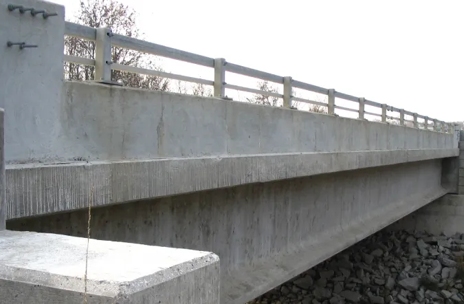
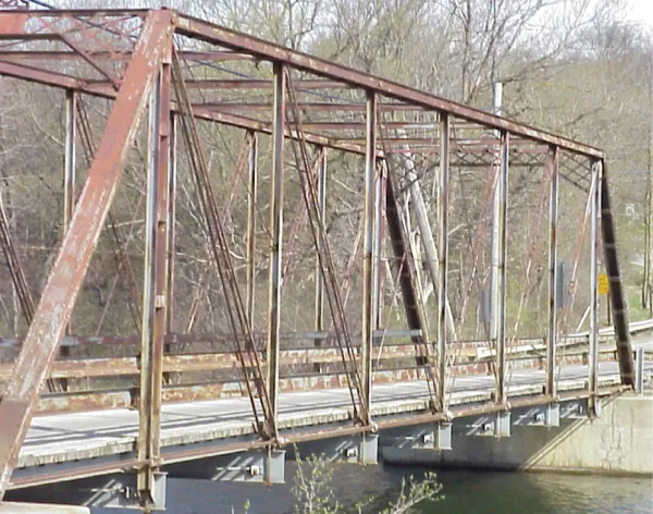
Based on the superstructure type, highway bridges may be recognized as slab bridges, beam or girder bridges, arch bridges, truss bridges, cable-stayed bridges, and suspension bridges. These names directly refer to the main spanning structure of the bridges. Namely, slab bridges use a slab to span the opening, beam or girder bridges use beams, arch and truss bridges use arches and trusses, cable-stayed bridges use cable-stayed main girders, and suspension bridges use suspension-supported main girders. Figures 1.2-1 to 1.2-7 illustrate some of these bridge types. More details of these bridge types will be presented in Chapter 4 on highway bridge superstructure.
It also should be mentioned that, by number of bridges and by number of spans, beam or girder bridges represent by far the most popular highway bridges in the United States and the world. Their span lengths are usually within 300 ft to be cost effective. For longer spans, arch, truss, cable-stayed, and suspension spans may become more preferred due to cost consideration. Some examples for these spans are shown in Figures 1.2-6 to 1.2-9. Typically more than 90% of highway bridges are beam or girder bridges in the United States. This percentage is larger for number of bridge spans because very long bridges often consist of many short or medium beam spans. Therefore, this introductory book on highway bridge design and evaluation focuses on beam or girder bridges of short and medium spans covering a vast majority of current highway systems.
It is also very common to classify bridges into different groups according to their superstructure type. For example, classification according to superstructure material is a common one. Thus, there are steel bridges, prestressed concrete bridges, timber bridges, aluminum bridges, and so on, referring to the major material used to construct the superstructure. Another common classification is based on superstructure configuration, such as continuous bridges and simple span bridges, referring to spans made of continuous beams and simply supported beams, respectively. Sometimes they are used to refer to truss spans as well because trusses can also be easily made continuous over a support. Segmental bridge refers to the construction method used: namely, these bridges are constructed using segments and assembled into a system. Usually segmental bridges have long spans that require the spans to be constructed by connecting small pieces (segments) to form the spans. It is thus important to ensure the connections in segmental bridges to be positive and reliable for many years to come. A typical approach to this type of construction is to use prestressing: pretensioning each segment to reduce the self-weight and posttensioning each segment to the part already in place during erection.
Note also that it is important to differentiate a bridge from a bridge span. A “bridge” refers to all the spans of the bridge. A “bridge span” refers to one of the possibly many spans of the bridge. Of course, when a bridge has only one span, that span is the bridge. Nevertheless, the word bridge sometimes also includes the approach spans at the two ends of the bridge as well as the substructure system near and below the ground. In that case, the word span often only means the superstructure and does not include other parts of the bridge system.
1.3 Bridge Construction and Its Relation to Design
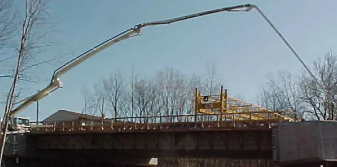
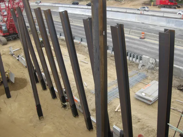
It is essential for a bridge designer to understand the planned construction process of the bridge being designed. It is very important that the designer take into account the construction procedure in the design process because the construction procedure may subject bridge components to loading conditions not experienced in service and these conditions require special design. For example, lifting a prestressed concrete beam as a primary component for a beam bridge using a crane may cause a significant negative moment that would never be induced in the service condition. Thus this negative moment needs to be carefully designed and detailed for. Otherwise, the beam may fail or be damaged during construction. This check in design is referred to as a constructability check in the AASHTO design specifications. Figures 1.3-1 to 1.3-3 show a few steps of highway bridge construction.
It is also worth mentioning that many bridge failure incidents occur when the bridge is under construction. Therefore, construction load is an important load to consider and to cover in design.
1.4 AASHTO Specifications and Design and Evaluation Methods
Load factor design (LFD) and service load design (SLD) were the two traditional design methods used in the United States for highway bridge design over many decades and prior to the current AASHTO specifications. Sometimes SLD is referred to as allowable stress design (ASD) in the literature. In 1994, AASHTO adopted the first edition of the LRFD Bridge Design Specifications with the load and resistance factor design (LRFD) method. As mentioned in the preface, the latest sixth edition (AASHTO, 2012) is exclusively referred to in this book. This set of design specifications is also referred to hereaf...