![]()
Chapter 1
Overview of Residual Stresses and Their Measurement
Gary S. Schajer1 and Clayton O. Ruud2
1University of British Columbia, Vancouver, Canada
2Pennsylvania State University, Washington, USA (Retired)
1.1 Introduction
1.1.1 Character and Origin of Residual Stresses
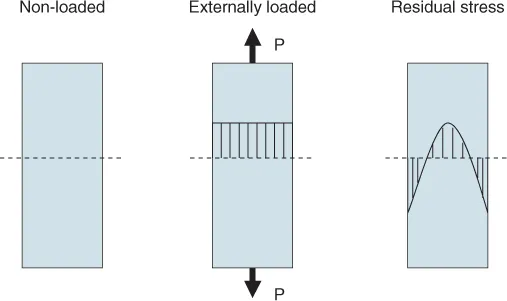
Residual stresses are “locked-in” stresses that exist in materials and structures, independent of the presence of any external loads [1]. The stresses are self-equilibrating, that is, local areas of tensile and compressive stresses sum to create zero force and moment resultants within the whole volume of the material or structure. For example, Figure 1.1 schematically illustrates how a residual stress distribution through the thickness of a sheet of toughened glass can exist without an external load. The tensile stresses in the central region balance the compressive stresses at the surfaces.
Almost all manufacturing processes create residual stresses. Further, stresses can also develop during the service life of the manufactured component. These stresses develop as an elastic response to incompatible local strains within the component, for example, due to non-uniform plastic deformations. The surrounding material must then deform elastically to preserve dimensional continuity, thereby creating residual stresses. The mechanisms for creating residual stresses include:
1. Non-uniform plastic deformation. Examples occur in manufacturing processes that change the shape of a material including forging, rolling, bending, drawing and extrusion, and in service during surface deformation, as in ball bearings and railway rails.
2. Surface modification. Examples occur in manufacture during machining, grinding, plating, peening, and carburizing, and in service by corrosion or oxidation.
3. Material phase and/or density changes, often in the presence of large thermal gradients. Examples occur in manufacture during welding, casting, quenching, phase transformation in metals and ceramics, precipitation hardening in alloys and polymerization in plastics, as well as in service from radiation damage in nuclear reactor components and moisture changes in wood.
Residual stresses are sometimes categorized by the length scale over which they equilibrate [2]. Type I are macro residual stresses that extend over distances from mm upwards. These are the “macro stresses” that appear in manufactured components. Type II are micro residual stresses that extend over distances in the micron range, for example, between grains in metals. Type I macro-stress, whether residual or applied, is one cause of Type II micro-stresses. Finally, Type III are residual stresses that occur at the atomic scale around dislocations and crystal interfaces. The Type I macro stresses are the target of most of the measurement techniques described in this book. Several of the techniques can be scaled down and used also to measure Type II and possibly Type III stresses. However, for some of the diffraction methods, the presence of Type II stresses can impair attempts to measure Type I stresses.
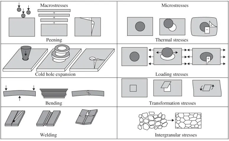
Figure 1.2 schematically illustrates examples of some typical ways in which residual stresses are created in engineering materials. The diagrams illustrate how localized dimension changes require the surrounding material to deform elastically to preserve dimensional continuity, thereby creating residual stresses. For example, the upper left panel illustrates shot peening, where the surface layer of a material is compressed vertically by impacting it with small hard balls [8]. In response, the plastically deformed layer seeks to expand horizontally, but is constrained by the material layers below. That constraint creates compressive surface stresses balanced by tensile interior stresses, as schematically shown in the graph. A similar mechanism occurs with plastic deformation created in cold hole expansion and bending, although with completely different geometry. Phase transformations, such as martensitic transformations in steel, can also cause the dimensions of a part of material to change relative to the surrounding areas, also resulting in residual stresses.
Solidification and differential shrinkage cause large tensile and compressive residual stresses in welds. The weld metal is stress-free while molten, and can support residual stresses only after solidification. The very hot weld metal and heat-affected zone (HAZ) cool over a larger temperature range than the surrounding cooler material and therefore shrinks more. Thus, to maintain dimensional continuity through compatible longitudinal strains, large longitudinal tensile residual stresses are created in the weld metal and HAZ balanced by compressive stresses in the surrounding material.
1.1.2 Effects of Residual Stresses
Because of their self-equilibrating character, the presence of residual stresses may not be readily apparent and so they may be overlooked or ignored during engineering design. However, they are stresses and must be considered in the same way as stresses due to external loading [6].
In terms of material strength, the main effect of residual stresses is as an addition to the loading stresses. The contribution of the residual stresses can be beneficial or harmful, dependent on the sign and location of the residual stresses. For example, the surface compressive residual stresses in the toughened glass shown in Figure 1.1 strengthen the overall structure because glass is brittle and has low tensile strength. The failure mechanism is by crack growth, but most cracks (scratches) are at the surfaces. Thus, the compressive residual stresses act to bias the loading stresses towards compression in the areas of the tension-sensitive surface cracks. There are few if any cracks in the central region and so the material there can tolerate the elevated local tensile stresses. The resultant effect of the combined stresses is an increased capacity of the glass component to support external loads. A similar concept applies to shot peening, where impacting a surface with small hard balls induces surface compressive stresses. An increased fatigue life is achieved by biasing the mean of the varying stresses at the surface towards compression, where fatigue cracks usually initiate.
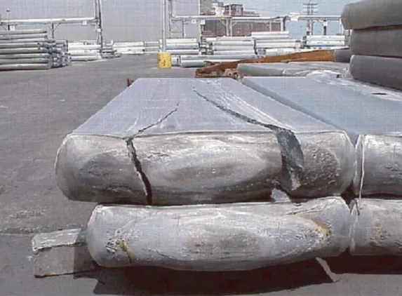
Residual stresses can also be harmful and significantly reduce material strength and cause premature fracture. Figure 1.3 shows longitudinal fractures in an aluminum alloy direct chill cast ingot, a precursor to hot rolling. The fractures are caused by residual stresses induced by inhomogeneous cooling after solidification during casting.
Some further examples of harmful effects of residual stresses are:
- Corrosion fatigue fracture of heart valves caused nearly 200 fatalities due to residual stresses induced by the bending of retainer struts during fabrication [9].
- Fatigue fractures enhanced by circumferential tensile residual stresses on rivet holes in a Boeing 737 caused the top half of the fuselage to be torn away with the loss of a flight attendant and injury to 65 passengers [10].
- Stress corrosion cracking of heat exchanger tubes in nuclear reactors caused loss of power production [11].
1.1.3 Residual Stress Gradients
Because residual stresses are non-zero but have zero force resultant, they must be non-uniform, sometimes quite substantially so, with large stress gradients.
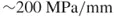
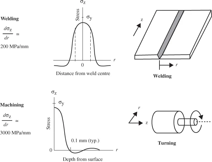
Figure 1.4 shows two examples of typical stress gradients found in manufactured components. The first shows welding residual stresses and indicates a stress gradient of
adjacent and parallel to the weld. The second example shows a machining stress gradient of ∼3000 MPa/mm from the surface to about 0.1 mm in depth.
Because of concerns for premature failure through fatigue and stress corrosion cracking, and because of the high stress gradients and the uncertainty of the area of highest stresses, it is often necessary to make many stress measurements on as small a number of elements of the component as possible. Thus, the spatial resolution and thickness of the measurement volume is an important consideration in most residual stress investigations, as is measurement speed and cost.
1.1.4 Deformation Effects of Residual Stresses
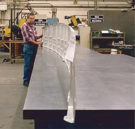
If a component containing residual stresses is cut in some way, the stresses with force components acting on the cut surface will relieve and the stresses within the remaining material will redistribute to maintain interior force equilibrium. The strains associated with the stress redistribution cause the component to distort, sometimes quite substantially [6, 7]. Figure 1.5 shows an example of an aircraft cargo ramp that had a major fraction of material removed to reduce structural weight. The particular forging contained residual stresses that were excessively large and/or very widespread, whose relief during machining caused the dramatic deformation shown in the photo. This deformation became apparent after the component was detached from the milling machine worktable.
Deformation of machined components due to release of residual stresses can be a serious problem, particularly when high dimensional precision is required. The most direct solution is to reduce the size of the residual stresses present either during material manufacture or by subsequent heat treatment. A further approach is to machine components incrementally, preferably symmetrically, and gradually converge on the desired dimensions.
The deformation caused by the residual stress redistribution after material cutting provides the basis of a major class of residual stress measurement methods, commonly called “relaxation” methods or “destructive” methods [2, 3]. By measuring the def...