![]()
PART 1
General Concepts
![]()
Chapter 1
Elements for the Design of Embedded Computer Systems
1.1. Introduction
The development of embedded systems is usually done using low-level languages: namely, assembly language and oftentimes C. The main reason for this is the need to elaborate programs that have a small memory footprint because they are usually deployed on very compact architectures1. More costly development techniques have been gradually created. These development techniques are mainly based on an in-depth assessment of the requirements, intensive tests as well as very strict development procedures, which ensure a safety standard satisfying the expectations of the general public.
However, these systems that often accomplished critical missions frequently involved very expensive developing strategies, thereby being limited to a specific usage such as space travel, aeronautics, nuclear use and railroad transportation. Once these systems emerged in more “mainstream” industries, the approaches in development had to evolve in a cost-reducing direction. The economic revolution toward offshore development does not facilitate these aspects of viability/safety, but these new development approaches could, in the long run, become very competitive.
The mere use of high-level programming languages is not, in and by itself, the solution. Embedded systems usually contain sophisticated mechanisms and runtime libraries. Because the latter cannot be certified, they are very difficult to use. Take the Ada language as an example of this. It was elaborated in the 1970s with the aim of developing low-cost embedded systems. Some of its features (usually the management of parallelism) have seen limited usage in certain fields, largely due to the code compiled having to be associated with limited runtimes (for instance, not being able to support the parallelism or the dynamic memory allocation).
One solution to maximising software viability and minimizing the cost of embedded computer systems is through the use of model-driven engineering (MDE). It indeed facilitates better interactions between the different languages and models used throughout the design/development cycle.
More particularly, it allows us to rely on dedicated “models”, which sometimes facilitate the reasoning process. Thus, engineers can predict certain behavioral aspects of their programs. The transformation techniques that have been developed by this community ensure the link between the different development stages.
These new approaches will not suddenly replace the existing procedures. The actors behind the development of embedded systems (particularly when they carry out critical missions) cannot afford to take any risks. However, these actors have gradually taken an interest in these new techniques and their application in adequate methodological frameworks.
In the long run, the objective is to reach high-performance industrial processes capable of ensuring trustable software, by providing, for instance, co-simulation and formal verification and allowing the target code generation to be validated right from the beginning of the modeling.
It should not surprise us that the three notations presented in this book – systems modeling language (SysML), unified modeling language/modeling and analysis of real-time and embedded systems (UML/MARTE), and architecture analysis and design language (AADL) – are heavily reliant on model engineering. Model engineering is clearly a “hot topic” in the community at the moment.
Chapter outline. This chapter discusses several elements that are important in the development of embedded systems in the context we have just touched upon. We pay particular attention to:
– the modeling activity (section 1.2);
– the presentation of the UML, which serves as the foundation for two of the three notations presented in this book (section 1.3);
– the presentation of the MDE (section 1.4);
– an overview of the analysis techniques and, in particular, those used in this book (section 1.5);
– the methodological aspects of system development (section 1.6).
1.2. System modeling
The modeling operation has been a widespread practice in the history of humanity. It seeks to explain the behavior of a complex system via a model that abstracts it. We can cite the different models designed for explaining celestial movements: the system of the epicycles, the Ptolemaic system, the Tycho Brahe system, the Copernican system, etc. Their objective was to predict the evolution of the planets’ position. They represent a process of ongoing fine-tuning of the understanding of a field, a new system replacing the old system when new evidence crops up showing that the old system does not correspond to reality. Modeling has, therefore, been an indispensable tool in experimental sciences for a long time.
In computer science, the big difference lies in the fact that the model does not reproduce a system we are trying to observe in order to understand its behavior. The model is placed at an earlier stage, and allows us to realize whether a solution, which is in the process of being discovered, will respect the properties expected.
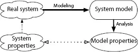
Figure 1.1. Relations between the system, its model and their properties
Figure 1.1 represents the relation between different entities of a system at the core of the modeling operation. The engineer models the system while he or she is in the process of designing it. The analysis of this model (via simulation or via more formal methods, see section 1.5.1) allows us to deduce system properties. However, the relation between the properties of the model and those of the system is by no means a trivial issue.
First, the expression of the properties may vary greatly in the two cases. Usually the property of the system will be expressed in a natural language, whereas the property of the model will have the shape of an invariant or will reference quite precisely an entity of the analysis (whose meaning must be known to the users if they wish to understand it). We must thus anticipate elements of traceability between the two.
Second, the necessary abstraction of certain system elements during the modeling process (for instance, changing from discrete types to continuous types) can, when done poorly, result in a model that does not faithfully represent the system. If it is a superset, then a property that has not been verified on the model can be verified on the system; if it is a subset, then a property that has been verified on the model may not be true for the system.
Modeling is thus a challenging operation that must be carried out carefully. More particularly, the modeling choices must be documented properly. In the field of embedded systems, we will introduce several important notions regarding the concept of a model.
Structural or behavioral modeling. The former defines the structure of a system (i.e. the class diagrams or the UML instances) whereas the latter describes its behavior. When examining problematic behaviors, or identifying emerging behaviors, we must reach the second level, which generally presupposes that the modeling of the system structure already exists (at least the identification of the interacting actors).
Open or closed models. An open model describes a system. A closed model describes the system and the environment it interacts with. We can, thus, consider that the open model is “included” in the closed model.
The reason we need to distinguish between the two is that we are able to subject the model of a system to different conditions of execution. Each of them is thus characterized by a dedicated specification of the environment that “closes” the specification. This notion is particularly useful when we study different execution modes: a nominal mode, modes that have been degraded as a consequence of certain conditions, etc.
Notations used in this book. This book deals with embedded systems and only uses the notations that enable us to describe those systems. Out of these, we have selected three. Of the three, SysML [OMG 12a] and MARTE [OMG 12b] are UML profiles, and AADL [SAE 09] is a dedicated notation that integrates, at the same time, the description of the software part and that of the hardware part of a system.
1.3. A brief presentation of UML
The first version of the UML was version 2.8 of the “unified method”, which was written by G. Booch and J. Rumbaugh. At the time, in 1995, Y. Jacobson was not yet part of the adventure, and the letter “M” stood for “method”.
A year later, the first versions of the UML, namely versions 0.9 and 0.91, were published, which incorporated the work of Y. Jacobson. This time, the “M” stood for “modeling”. Indeed, these three “fabulous evangelists”, having not agreed upon one standard method, had instead focused on the notation.
UML 1.0 and 1.1 were proposed to the Object Management Group (OMG) in 1997. Then came version 1.2 in 1998, 1.3 (a very significant revision) in 1999, 1.4 in 2001 and, finally, 1.5 in 2002. This sequence of different versions is usually called “UML1.X”. This was followed by UML 2.X, whose first stable version (2.0), appeared in 2003. This is a major revision now involving 13 diagrams instead of nine previously. The metamodel was also considerably modified (which is of relevance to tool designers). The notion of the profile was formalized, which has allowed, for example, the emergence of “variants”, such as SysML and MARTE, which we will detail in this chapter.
Let us note that the transition from 1.X to 2.X, which was supposed to facilitate the use and efficiency of the language, has given mixed results. The industry and the toolmakers had put a significant amount of time into fully supporting UML 1.X and the required adaptation has delayed the operational use of UML 2.X, which has only recently begun to be used effectively in industry.
We will introduce the main UML characteristics (in its current version in 2012, the 2.4.1 version). The 16 UML diagrams are divided into two classes: static and dynamic diagrams.
Among these 13 diagrams, the four “main” diagrams are considered to be classes, sequence, use cases and state machines. They are used in the parts dedicated to SySML and to MARTE but also, systematically, by all the UML users.
UML is a notation. To use it well, we also need a method. Thus, each company has created its own method usually relying on the “unified” method (UM) or the rational unified process (RUP) (the two are pretty close). These methods describe when and how to use this or that diagram, how to organize the model as well as the documents and the codes that are generated while still respecting the specification/design processes that are enforced throughout the enterprise such as traceability, configuration management and quality (rules for a correct usage, coding rules, etc.).
1.3.1. The UML static diagrams
These diagrams describe the static aspects of ...