![]()
Part One
Content Creation
![]()
1
Consumer Depth Cameras and Applications
Seungkyu Lee
Samsung Advanced Institute of Technology, South Korea
1.1 Introduction
Color imaging technology has been advanced to increase spatial resolution and color quality. However, its sensing principle limits three-dimensional (3D) geometry and photometry information acquisition. Many computer vision and robotics researchers have tried to reconstruct 3D scenes from a set of two-dimensional (2D) color images. They have built a calibrated color camera network and employed visual hull detection from silhouettes or key point matching to figure out the 3D relation between the set of 2D color images. These techniques, however, assume that objects seen from different views have identical color and intensity. This photometry consistency assumption is valid only for Lambertian surfaces that are not common in the real world. As a result, 3D geometry data capture using color cameras shows limited performance under limited lighting and object environments.
3D sensing technologies such as digital holograph, interferometry, and integral photography have been studied. However, they show limited performance in 3D geometry and photometry acquisition. Recently, several consumer depth-sensing cameras using near-infrared light have been introduced in the market. They have relatively low spatial resolution compared with color sensors and show limited sensing range and accuracy. Thanks to their affordable prices and the advantage of direct 3D geometry acquisition, many researchers from graphics, computer vision, image processing, and robotics have employed this new modality of data for many applications. In this chapter, we introduce two major depth-sensing principles using active IR signals and state of the art applications.
1.2 Time-of-Flight Depth Camera
In active light sensing technology, if we can measure the flight time of a fixed-wavelength signal emitted from a sensor and reflected from an object surface, we can calculate the distance of the object from the sensor based on the speed of light. This is the principle of a time-of-flight (ToF) sensor (Figure 1.1). However, it is not simple to measure the flight time directly at each pixel of any existing image sensor. Instead, if we can measure the phase delay of the reflected signal compared with the original emitted signal, we can calculate the distance indirectly. Recent ToF depth cameras in the market measure the phase delay of the emitted infrared (IR) signal at each pixel and calculate the distance from the camera.
1.2.1 Principle
In this section, the principle of ToF depth sensing is explained in more detail with simplified examples. Let us assume that we use a sinusoidal IR wave as an active light source. In general, consumer depth cameras use multiple light-emitting diodes (LEDs) to generate a fixed-wavelength IR signal. What we can observe using an existing image sensor is the amount of electrons induced by collected photons during a certain time duration. For color sensors, it is enough to count the amount of induced electrons to capture the luminance or chrominance of the expected bandwidth. However, a single shot of photon collection is not enough for phase delay measurement. Instead, we collect photons multiple times at different time locations, as illustrated in Figure 1.2.
Q1 through
Q4 in
Figure 1.2 are the amounts of electrons measured at each corresponding time. Reflected IR shows a phase delay proportional to the distance from the camera. Since we have reference emitted IR and its phase information, electron amounts at multiple time locations (
Q1 through
Q4 have a 90
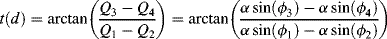
phase difference to each other) can tell us the amount of delay as follows:
where α is the amplitude of the IR signal and ϕ1 through ϕ4 are the normalized amounts of electrons.
In real sensing situations, a perfect sine wave is not possible to produce using cheap LEDs of consumer depth cameras. Any distortion on the sine wave causes miscalculation of the phase delay. Furthermore, the amount of electrons induced by the reflected IR signal at a certain moment is very noisy due to the limited LED power. In order to increase the signal-to-noise ratio, sensors collect electrons from multiple cycles of reflected IR signal, thus allowing some dedicated integration time.
For a better understanding of the principle, let us assume that the emitted IR is a square wave instead of sinusoidal and we have four switches at each sensor pixel to collect
Q1 through
Q4. Each pixel of the depth sensor consists of several transistors and capacitors to collect the electrons generated. Four switches alter the on and off states with 90
phase differences based on the emitted reference IR signal as illustrated in
Figure 1.3. When a switch is turned on and reflected IR goes high, electrons are charged as indicated by shaded regions.
In order to increase the signal-to-noise ratio, we repeatedly charge electrons through multiple cycles of the IR signal to measure Q1 through Q4 during a fixed integration time for a single frame of depth image acquisition. Once Q1 through Q4 are measured, the distance can be calculated as follows:
where c is the speed of light (3 × 10⁸ m/s) and t(d) is the flight time. Note that q1 through q4 are normalized electric charges and α is the amplitude of reflected IR that does not affect the distance calculation. In other words, depth can be calculated correctly regardless of IR amplitude. The emitted IR should be modulated with a high enough frequency to estimate the flight time.
As indicated in Figure 1.4, what we have calculated is the distance R from the camera to an object surface along the reflected IR signal. This is not necessarily the distance along the z-direction of the 3D sensor coordinate. Based ...