![]()
Chapter 1
Overview of Cortex-M3 Architecture
A computer program is usually defined as a sequence of instructions that act on data and return an expected result. In a high-level language, the sequence and data are described in a symbolic, abstract form. It is necessary to use a compiler to translate them into machine language instructions, which are only understood by the processor. Assembly language is directly derived from machine language, so when programming in assembly language the programmer is forced to see things from the point of view of the processor.
1.1. Assembly language versus the assembler
When executing a program, a computer processor obeys a series of numerical orders – instructions – that are read from memory: these instructions are encoded in binary form. The collection of instructions in memory makes up the code of the program being executed. Other areas of memory are also used by the processor during the execution of code: an area containing the data (variables, constants) and an area containing the system stack, which is used by the processor to store, for example, local data when calling subprograms. Code, data and the system stack are the three fundamental elements of all programs during their execution.
It is possible to program directly in machine language – that is, to write the bit instruction sequences in machine language. In practice, however, this is not realistic, even when using a more condensed script thanks to hexadecimal notation (numeration in base 16) for the instructions. It is therefore preferable to use an assembly language. This allows code to be represented by symbolic names, adapted to human understanding, which correspond to instructions in machine language. Assembly language also allows the programmer to reserve the space needed for the system stack and data areas by giving them an initial value, if necessary. Take this example of an instruction to copy in the no. 1 general register of a processor with the value 170 (AA in hexadecimal). Here it is, written using the syntax of assembly language studied here:
EXAMPLE 1.1. – A single line of code
MOV Rl, #OxAA ; copy (move) value 170 (AA in hexa) ; in register Rl
The same instruction, represented in machine language (hexadecimal base), is written: E3A010AA. The symbolic name MOV takes the name mnemonic. R1 and #0xAA are the arguments of the instruction. The semicolon indicates the start of a commentary that ends with the current line.
The assembler is a program responsible for translating the program from the assembly language in which it is written into machine language. Upon input, it receives a source file that is written in assembly language, and creates two files: the object file containing machine language (and the necessary information for the fabrication of an executable program), and the printout assembly file containing a report that details the work carried out by the assembler.
This book deals with assembly language in general, but focuses on processors based on Cortex-M3, as set out by Advanced RISC Machines (abbreviated to ARM). Different designers (Freescale, STmicroelectronics, NXP, etc.) then integrate this structure into µcontrollers containing memory and multiple peripherals as well as this processor core. Part of the documentation regarding this processor core is available in PDF format at www.arm.com.
1.2. The world of ARM
ARM does not directly produce semiconductors, but rather provides licenses for microprocessor cores with 32-bit RISC architecture.
This Cambridge-based company essentially aims to provide semiconductors for the embedded systems market. To give an idea of the position of this designer on this market, 95% of mobile telephones in 2008 were made with ARM-based processors. It should also be noted that the A4 and A5 processors, produced by Apple and used in their iPad graphics tablets, are based on ARM Cortex-Type A processors.
Since 1985 and its first architecture (named ARM1), ARM architectures have certainly changed. The architecture upon which Cortex-M3 is based is called ARMV7-M.
ARM’s collection is structured around four main families of products, for which many licenses have been filed1:
– the ARM 7 family (173 licenses);
– the ARM 9 family (269 licenses);
– the ARM 10 family (76 licenses);
– the Cortex-A family (33 licenses);
– the Cortex-M family (51 licenses, of which 23 are for the M3 version);
– the Cortex-R family (17 licenses).
1.2.1. Cortex-M3
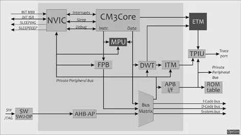
Cortex-M3 targets, in particular, embedded systems requiring significant resources (32-bit), but for these the costs (production, development and consumption) must be reduced. The first overall illustration (see Figure 1.1) of Cortex-M3, as found in the technical documentation for this product, is a functional diagram. Although simple in its representation, every block could perplex a novice. Without knowing all of the details and all of the subtleties, it is useful to have an idea of the main functions performed by different blocks of the architecture.
1.2.1.1. Executive units
These units make up the main part of the processor – the part that is ultimately necessary to run applications and to perform them or their software functions:
– CM3CORE: This is the core itself. This unit contains different registers, all of the read/write instruction mechanisms and data in the form of the arithmetical and logical unit for the proper execution of different instructions. The functioning of this block will be explained in detail in Chapter 2. It is necessary to understand its mechanism in order to write programs in assembly language.
– Nested Vector Interrupt Controller (NVIC): Cortex-M3 is intended to be embedded in a
µcontroller, which includes peripheral units to allow interfacing with the outside world. These units can be seen as independent micromachines. The exchanges between them and Cortex-M3 must consequently be rhythmic and organized so that the sequence of tasks complies with rules (the concept of priorities) and determinism set in advance by the programmer. NVIC plays the role of “director”. It is in charge of receiving, sorting and distributing the different interrupt requests generated by the collection of
µcontroller units. It also manages events that threaten the smooth running of the code being executed (reset, memory bus problem, division by 0, etc.).
– Memory Protection Unit (MPU): This block is optional – a designer using Cortex-M3 to make their µcontroller can choose not to implement this function. This block allows the allocation of specific read and/or write privileges to specific memory zones. In this way, when different independent software tasks are executed in parallel (or more precisely in sharing the common resources of the processor), it is possible to allocate a memory zone to each task that is inaccessible to the other tasks. This mechanism therefore allows programmer to secure memory access. It usually goes hand-in-hand with the use of an operating system (real-time or otherwise) for the software layer.
– Bus matrix: This unit is a kind of gigantic intelligent multiplex. It allows connections to the external buses:
- the ICode bus (32-bit AHB-Lite type2) that carries the memory mappings allocated to the code and instructions;
- the DCode bus (also 32-bit AHB-Lite type) that is responsible for reading/writing in data memory zones;
- the System bus (again 32-bit AHB-Lite type), which deals with all system space access;
- the Private Peripheral Bus (PPB): all peripherals contained in the µcontroller are added to the Cortex-M3 architecture by the designer. ARM designed a specific bus to allow exchanges with peripherals. This bus contains 32 bits, but in this case it is the Advanced Peripheral Bus (APB) type. This corresponds to another bus protocol (which you may know is less efficient than AHB type, but it is more than sufficient for access to peripheral units). It should be noted that the bus matrix plays an important role in transmitting useful information to development units, which are mentioned in the next section.
1.2.1.2. Development units
The development of programs is an important and particularly time-consuming step in the development cycle of an embedded application. What is more, if the project has certification imperatives, it is necessary that tools (software and/or material) allowing maximum monitoring of the events occurring in each clock cycle are at its disposition. In Cortex-M3, the different units briefly introduced below correspond to these monitoring functions. They are directly implanted in the silicon of the circuit, which allows them to use these development tools at a material level. An external software layer is necessary, however, to recover and process the information issued by these units. The generic idea behind the introduction of hardware solutions is to offer the programmer the ability to test and improve the reliability of (or certify) his or her code without making any changes. It is convenient (and usual) to insert some print (“Hello I was here”) into a ...