CO2 capture and geological storage is seen as the most effective technology to rapidly reduce the emission of greenhouse gases into the atmosphere. Up until now and before proceeding to an industrial development of this technology, laboratory research has been conducted for several years and pilot projects have been launched. So far, these studies have mainly focused on transport and geochemical issues and few studies have been dedicated to the geomechanical issues in CO2 storage facilities. The purpose of this book is to give an overview of the multiphysics processes occurring in CO2 storage facilities, with particular attention given to coupled geomechanical problems. The book is divided into three parts. The first part is dedicated to transport processes and focuses on the efficiency of the storage complex and the evaluation of possible leakage paths. The second part deals with issues related to reservoir injectivity and the presence of fractures and occurrence of damage. The final part of the book concerns the serviceability and ageing of the geomaterials whose poromechanical properties may be altered by contact with the injected reactive fluid.
Trusted by 375,005 students
Access to over 1.5 million titles for a fair monthly price.
Assessing Seal Rock Integrity for CO2 Geological Storage Purposes
1.1. Introduction
Prior to any CO2 geological storage project, an assessment is needed to confirm the ability of the formations overlying the storage reservoir to act as a seal with respect to the underlying pressurized CO2. In the case of hydrocarbon reservoirs, these formations typically consist of low-permeability caprocks: the ability of these tight rocks (usually imbibed with water) to act as a seal with respect to an underlying buoyant phase is primarily a capillary effect, which is indeed proven in the case of the hydrocarbon phase present in the reservoir, but not in the case of a CO2-rich phase. In the case of deep saline aquifers, the sealing efficiency of the overlying tight formations (referred to as aquitards or aquicludes) with respect to a non-aqueous buoyant fluid is not known.
Excessive pressurization of the CO2 phase, due to the injection operations and to the buoyancy effect, induces leakage through the seal rock(s) by a variety of mechanisms, each being active above a specific pressure threshold. The lowest of these thresholds should indeed not be exceeded during the CO2 injection and storage operations – unless the associated leakage rate is extremely small.
The failure mechanisms are conventionally divided into two types: mechanical and capillary. Seals that fail because of mechanical and capillary mechanisms are referred to as hydraulic seals and membrane seals, respectively [WAT 87]. Mechanical failure comprises the development of high-permeability pathways through a variety of processes, such as tensile fracturing or shear slip reactivation of pre-existing faults, as well as thermal fracturing. This is considered to be the most dangerous failure mode, with high associated leakage rates, and it is constantly monitored in most ongoing CO2 storage projects, e.g. by passive microseismic techniques (see [RUT 12] for a recent review).
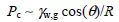
Capillary failure (or capillary invasion), in which the rock pore structure is left unaltered during (and after) the gas leakage process, is a more pervasive process than mechanical failure, and lower leakage rates are expected – the effective gas permeability that follows gas capillary breakthrough is only a fraction of the intrinsic permeability of the seal rock, which itself does (or should) not exceed a few micro-Darcy (10–18 m2). It is expected to occur at a lower CO2 (pore) pressure than the pressure required for tensile fracturing, except in extremely tight rocks such as evaporites [GLU 04]. This pressure corresponds to the capillary entry pressure, or the minimum overpressure in the CO2 phase (compared to brine pressure) required to intrude into the seal rock and to displace the saturating brine phase. From the Laplace–Young equation, this overpressure, hereafter denoted by Pc, is inversely proportional to a characteristic pore throat size R and proportional to the interfacial tension (IFT) between the brine and the stored CO2-rich gas (γw,g) and to the cosine of the contact angle θ characterizing the wettability of the seal rock:
[1.1]
More precisely, θ is the water-receding (or gas-advancing) angle on the rock substrate, which is referred to in the following as the drainage angle. This angle is often significantly smaller than the imbibition angle corresponding to the reverse displacement (water displacing the CO2-rich fluid from the substrate): the difference, or contact angle hysteresis, is related in a complex manner to the interactions of CO2 with the substrate, and to substrate chemical and/or geometrical heterogeneities.
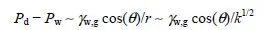
In practice, the sealing capacity of a tight rock (sampled for instance from the overburden of a potential storage site) initially saturated with brine is appreciated in the laboratory from breakthrough or displacement experiments. This sort of experiment is carried out in a more general context, e.g. for qualifying the confining properties of the engineered (compact) clay barriers used for underground nuclear waste disposal (here, the gas is the hydrogen generated by the waste) [GAL 98, HAR 99, HOR 99, GAL 00], or of the upper layers of underground reservoirs for seasonal storage of natural gas. The “standard” procedure [THO 68] for running such experiments consists of increasing stepwise the gas pressure on one face of a brine-saturated rock sample until the gas starts penetrating into the sample and thus displaces the saturating brine, which defines the gas entry pressure, and then, for a slightly larger pressure threshold called breakthrough or displacement pressure, comes out on the other face of the sample; then, the effective gas permeability after breakthrough can also be determined. The gas (CO2) breakthrough (or displacement) pressure, hereafter denoted as Pd, and the effective gas permeability after breakthrough are very important in practice, as they are related, respectively, to the maximum sustainable overpressure in the storage reservoir and to the leakage rate of the CO2-rich fluid following breakthrough (Pd can be exceeded, however, if this rate is extremely small). If it is assumed that the capillary invasion process described in the previous paragraph is the dominant failure mechanism (i.e. the seal rock is a membrane seal), then Pd should obey the following Laplace–Young equation:
[1.2]
where Pw is the pressure in the brine that imbibes the seal rock, r is the size of the narrowest pore throats along the leakage pathway in the seal rock, and k < r1/2 is the intrinsic (or absolute) permeability of the seal rock. In addition to being very tight (r and k small), the interfacial tension between brine and the CO2-rich gas must be high enough and the seal rock must be water-wet (i.e. small θ) if the brine-saturated rock is to function as an effective (membrane) seal with respect to the buoyant CO2-rich phase. On the one hand, the available evidence is that IFTs between brine and CO2 in geological storage conditions are higher than ~23 mN/m – this value has to be corrected for the effects of the impurities co-injected with CO2 and of the mixing with indigenous hydrocarbons (if storage is in a hydrocarbon reservoir). On the other hand, the water-wet character of many rocks and rock-bearing minerals seems to be preserved in the presence of CO2, at least in the drainage conditions (CO2 displaces water from the substrate) representative of the leakage process. This subject is currently being intensely investigated.
The outline of this chapter is as follows: the “standard” procedure for determining gas breakthrough (or displacement) pressures in water-saturated tight rocks and the ensuing gas effective permeability is presented in section 1.2. This determination, which is extremely time-consuming, is mandatory in the case of deep aquifers where there is no a priori knowledge of the sealing behavior of the top aquitard (or aquiclude), but it can be skipped in the case of hydrocarbon reservoirs where a lower bound on breakthrough pressure can be simply inferred from the reservoir discovery pressure and the relevant interfacial properties. These properties, namely the IFTs between brine and CO2-rich fluids and the wetting (contact) angle θ, are reviewed and discussed in section 1.3, and the method for inferring a lower bound on the CO2 breakthrough pressure of depleted hydrocarbon reservoirs is presented in section 1.4. In section 1.5, the gas breakthrough experiments available in the literature are further examined and discussed. It turns out that the mechanism of capillary invasion in a rigid porous medium (i.e. membrane seal failure) does not account for many of the observed features, which witness some quasi-permanent deformations of the porous structure.
The important topics of mechanical failure processes such as thermal fracturing, reconnection of fracture networks, and shear reactivation of faults (especially when a reactive fluid, i.e. CO2 and water, changes the slip conditions) are not addressed in this chapter (see [RUT 12] for a review).
1.2. Gas breakthrough experiments in water-saturated rocks
The standard procedure [THO 68] for determining the gas breakthrough (or displacement) pressure in a given rock sample fully saturated with brine and placed in representative temperature and confining pressure conditions consists of increasing the gas pressure in a stepwise fashion (each step lasting a few hours to a few days) on one face of the sample until the breakthrough pressure is reached, i.e. gas displaces the saturating brine phase across the sample [LI 05, HAR 09, TON 10, TON 11, BOU 11, SKU 12]. Gas entry (but no breakthrough) may occur for the pressure step previous to breakthrough, i.e. the gas phase enters the rock, but does not come out on the other face of the sample. Most gas displacement experiments are conducted with nitrogen as the gas phase rather than with CO2: then, the CO2-breakthrough overpressure is obtained by multiplying the nitrogen-breakthrough overpressure by the ratio of the brine-CO2 IFT to the brine-nitrogen IFT (assuming contact angles to be the same for the two gases: this point is discussed at the end of the following section).
In practice, the cylindrical (thin) rock sample to be tested is placed in a Hassler-type cell and fully saturated with brine under a prescribed representative confining pressure (this confining pressure or, more precisely, the effective pressure, i.e. the difference between the confining and pore pressures, has a strong impact on the rock petro-physical properties of interest; see [TON 10, TON 11, SKU 12]). The intrinsic permeability can then be determined, e.g. from steady-state measurements of the brine flow rate versus pressure drop across the sample [BOU 12]. Then, the gas phase is brought into contact with the inlet face of the sample and compressed in a stepwise manner, while a constant backpressure Pw is imposed in the brine phase on the outlet face, e.g. by means of a syringe pump working in the constant-pressure mode (the flow line from the sample outlet to the syringe is filled with the brine phase). Figur...
Table of contents
Cover
Contents
Title page
Copyright page
Preface
PART 1: Transport Processes
PART 2: Fracture, Deformation and Coupled Effects
PART 3: Aging and Integrity
List of Authors
Index
Frequently asked questions
Yes, you can cancel anytime from the Subscription tab in your account settings on the Perlego website. Your subscription will stay active until the end of your current billing period. Learn how to cancel your subscription
No, books cannot be downloaded as external files, such as PDFs, for use outside of Perlego. However, you can download books within the Perlego app for offline reading on mobile or tablet. Learn how to download books offline
Perlego offers two plans: Essential and Complete
Essential is ideal for learners and professionals who enjoy exploring a wide range of subjects. Access the Essential Library with 800,000+ trusted titles and best-sellers across business, personal growth, and the humanities. Includes unlimited reading time and Standard Read Aloud voice.
Complete: Perfect for advanced learners and researchers needing full, unrestricted access. Unlock 1.5M+ books across hundreds of subjects, including academic and specialized titles. The Complete Plan also includes advanced features like Premium Read Aloud and Research Assistant.
Both plans are available with monthly, semester, or annual billing cycles.
We are an online textbook subscription service, where you can get access to an entire online library for less than the price of a single book per month. With over 1.5 million books across 990+ topics, we’ve got you covered! Learn about our mission
Look out for the read-aloud symbol on your next book to see if you can listen to it. The read-aloud tool reads text aloud for you, highlighting the text as it is being read. You can pause it, speed it up and slow it down. Learn more about Read Aloud
Yes! You can use the Perlego app on both iOS and Android devices to read anytime, anywhere — even offline. Perfect for commutes or when you’re on the go. Please note we cannot support devices running on iOS 13 and Android 7 or earlier. Learn more about using the app
Yes, you can access Geomechanics in CO2 Storage Facilities by Gilles Pijaudier-Cabot,Jean-Michel Pereira in PDF and/or ePUB format, as well as other popular books in Technology & Engineering & Environmental Management. We have over 1.5 million books available in our catalogue for you to explore.