![]()
1
Introduction
In this chapter, we describe the historical developments that led to the evolution of inductance as a concept in electrical engineering. We introduce the laws of electromagnetism which are used throughout the book. Magnetic materials that are in common use today for inductors and transformers are also discussed.
1.1 Historical Context
In 1820, Oersted discovered that electric current flowing in a conductor produces a magnetic field. Six years later, Ampere quantified the relationship between the current and the magnetic field. In 1831, Faraday discovered that a changing magnetic field causes current to flow in any closed electric circuit linked by the magnetic field, and Lenz showed that there is a relationship between the changing magnetic field and the induced current. Gauss established that magnetic poles cannot exist in isolation. These phenomena established the relationship between electricity and magnetism and became the basis for the science of electromagnetism.
In 1865, Maxwell unified these laws in the celebrated form of Maxwell's equations, which established the basis for modern electrical engineering. He also established the link between phenomena in electromagnetics and electrostatics. Father Nicholas Joseph Callan, who was Professor of Natural Philosophy at the National University of Ireland, Maynooth, in the 1830 s, invented the induction coil. Alexander Anderson was Professor of Natural Philosophy at the National University of Ireland, Galway in the early 1900 s and gave his name to the Anderson Bridge for measuring inductance.
These individuals provide the inspiration for a textbook on magnetic design that focuses on the issues that arise in power electronics. Power electronics is an enabling technology for modern energy conversion systems and inductors and transformers are at the heart of these systems.
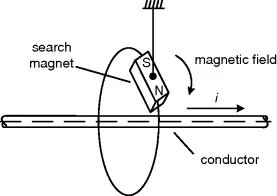
Figure 1.1 shows a straight conductor carrying a current, i. The presence of the magnetic field is detected by placing a freely-suspended magnet in the vicinity of the conductor. The direction of the magnetic field (a vector) is given by the direction in which the north pole of the search magnet points. It turns out that the magnitude of the magnetic field is constant on any circle concentric with the conductor, and its direction is tangential to that circle, given by the right hand rule – that is, a conventional (right-handed) cork screw will rotate in the direction of the magnetic field if it is driven in the direction of the current flow. It also turns out that the magnitude of the magnetic field is proportional to the current in the conductor and is inversely proportional to the radial distance from the conductor axis.
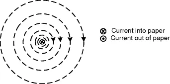
The magnetic field around a straight conductor is illustrated in Figure 1.2. The direction of the magnetic field as shown complies with the right hand screw rule. An alternative to the right hand screw rule for establishing the direction of the magnetic field created by the current is to point the thumb of your right hand along the conductor in the direction of the current flow, and your fingers will wrap themselves around the conductor in the direction of the magnetic field. The higher density of the lines near the conductor indicates a stronger magnetic field in this area.
The magnetic field around the current carrying conductor is described by two vector quantities: the magnetic flux density B and the magnetic field intensity H.
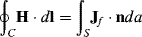
The magnetic field intensity H is best explained by Ampere's law, which expresses these observations about the current-carrying conductor in their most general form:
The closed contour C, the surface S and the normal vector are defined by convention: S is the surface enclosed by C and n is the unit vector normal to S. H is the magnetic field intensity in A/m and Jf is the current density in A/m2. The quantity on the right hand side of Equation 1.1 is the current enclosed by the contour.
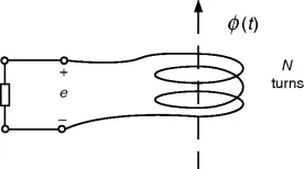
Figure 1.3 shows a coil with N turns in a magnetic field. The magnetic flux that links each turn of the coil is ϕ and the electromotive force (emf) induced in the coil is given by:
This states that the induced electromotive force (emf) in a coil of N turns is proportional to the rate of change of the magnetic flux that links the coil. The negative sign indicates that current flow in the external circuit will create an opposing magnetic field.
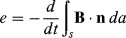
In a more general form, Equation 1.2 may be stated as:
The integral in Equation 1.3 represents the flux linking the coil. The surface S and the normal vector are defined as before. The flux density B in Wb/m2 or tesla is the flux per unit area inside the coil.
The magnetic field intensity H gives rise to a magnetic flux density B in a medium of permeability μ, so that:
The units for permeability are H/m and for free space μ0 = 4π × 10–7 H/m. For magnetic media, μ could be up to 10 000 times greater than μ0. The permeability is usually presented as the product of μ0 and the relative permeability μr.
Typically, relative permeability ranges from about 400 for ferrites used for power electronics applications to 10 000 for silicon steel that is used in power transformers at 50 Hz or 60 Hz. μr is taken as 1 for air. Permeability is treated in Section 1.5.
1.2 The Laws of Electromagnetism
In Maxwell's equations, t...