This book focuses on components such as filters, transformers, amplifiers, mixers, and oscillators. Even the phase lock loop chapter (the last in the book) is oriented toward practical circuit design, in contrast to the more systems orientation of most communication texts.
Trusted by 375,005 students
Access to over 1.5 million titles for a fair monthly price.
The design of radio frequency (RF) circuits borrows from methods used in low frequency audio circuits as well as from methods used in design of microwave circuits. However, there are also important departures from audio and microwave frequency methods, so that design of radio frequency circuits requires some specialized techniques not found in these other frequency ranges. The radio frequency range for present purposes will be taken to be approximately somewhere between 300 MHz and 3 GHz. It is this frequency range where much of the present day activity in wireless communication occurs. In this range of frequencies, the engineer must be concerned with radiation, stray coupling, and frequency response of circuit elements that, from the point of view of lumped, low frequency analysis, might be expected to be independent of frequency. At the same time, the use of common microwave circuit elements such as quarter wave transformers is impractical because of the long line lengths required. The use of monolithic circuits have enabled many high frequency designs to be implemented with lumped elements, yet the frequency response of these “lumped” elements still must be carefully considered. The small size of lumped elements in integrated circuits has provided practical designs of filters, transformers, couplers, etc. in lumped element form. Therefore discussion of designs for low noise amplifiers, power amplifiers, oscillators, mixers, and phase lock loops will be addressed with both lumped and distributed elements. Several of the numerical examples given in the text use computer programs. Source code for these programs are available on the web*. However, before getting into the details in the design of radio frequency circuits, it is important to understand that the purpose for these circuits is to transmit information.
1.2 INFORMATION AND CAPACITY
What exactly is information? Random House Dictionary 1966 states that “information” is “knowledge communicated or received concerning a particular fact or circumstance. …” A narrower technical definition more closely aligns with the focus given here is that “information” is an “indication of the number of possible choices of messages, expressible as the value of some monotonic function of the number of choices, usually log to the base 2.” Information then is a term for data that can be coded for digital processing.
Some examples of data that illustrate the meaning of information is helpful. If a signal were sent through a communication channel that never changed, then it would be conveying no information. There must be change to convey a message. If the signal consisted of 1 0 1 0 1 0 1 0 … , there would be changes in the signal but still no information is conveyed because the next bit would be perfectly predictable. So while change is important, it is not the sole criterion for information. There is one last example. If a signal in an amplitude modulation system consists of purely random voltage fluctuations, then again no information is being transmitted. It is simply noise, and the receiver is no more knowledgeable after having heard it.
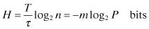
A communication system consists of a transmitter, a receiver, and a channel. The channel is capable of carrying only a certain limited amount of information. A water pipe can be seen as a rough analogy to a communication channel. The limitation in a communication channel is given the technical term capacity. It refers to the amount of information that is transmitted over a time interval of T seconds. The time interval can be broken up into short time intervals, each of duration τ. Clearly, the more distinct time intervals τ there are in the total time span T, the more information that can be transmitted. The minimum size of τ is determined by how well one pulse in one time frame can be distinguished from a pulse in a neighboring time frame. The limitation on how short a time frame can be is related to the channel bandwidth. In the water pipe analogy, the channel bandwidth corresponds to the pipe diameter.
In addition, the signal voltage will have a maximum amplitude that is limited by the available power in the system. This voltage range can be divided into many levels, each level representing a bit of information that is distinguished from another bit. The voltage range cannot be split indefinitely because of the noise that is always present in the system. Clearly, the more voltage intervals in a given time frame τ, the more information capacity there is in the system. Just as the flow of water through a pipe is limited by the amount of pressure on the water, by the friction on the walls of the pipe, and by the diameter of the pipe, so the capacity of a transmission system is limited by the maximum voltage level, by the noise in the system that tends to muddle the distinction between one voltage level and another, and by the bandwidth of the channel, which is related to the rise time of a pulse in the system.
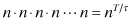
In one of the time intervals, τ, there are n voltage levels. The smaller that τ is and the larger n is, the more information that can be transmitted through the channel. In each time interval, there are n possible voltage levels. In the next time interval there are also n possible voltage levels. It is assumed that the voltage level in each time frame is independent of what is going on in other time frames. The amount of information transmitted in a total of T seconds corresponds to the products of the possibilities in each interval:
(1.1)
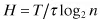
The total information, H, transmitted intuitively is directly proportional to the total time span T, and is defined as the log of the above product. By convention, the base 2 logarithm is used.
(1.2)
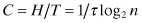
The system capacity is simply the maximum rate of transmission (in bits/s) through a system:
(1.3)
System capacity is inversely proportional to the minimum time interval over which a unit of information can be transmitted, τ. Furthermore, as the number of voltage levels increases, so does the capacity for more information.
Information can be transmitted through a channel in a variety of different forms, all giving the same amount of information. For example, suppose that a signal can take on any one of eight different voltage levels, 0,1, … , 7, in a given time interval τ. But the eight-level signal could also equally be sent with just two levels, 0,1. However, for every interval that has eight possible levels, three intervals will be needed for the two-level signal. A convenient conversion between the two systems is shown in Table 1.1.
TABLE 1.1 Eight-Level and Two-Level Systems
n = 8
n = 2
0
000
1
001
2
010
3
011
4
100
5
101
6
110
7
111
Clearly, a 16-level signal could be transmitted by a sequence of 4 binary signals, and a 32-level signal with a sequence of 5 binary signals, and so on. For n levels, log2n bits are needed. The information content of a signal is defined then to be the number of binary choices, or bits, that are needed for transmission. A system that is designed to transmit speech must be designed to have the capacity to transmit the information contained in the speech. While speech is not the total of what humans communicate, in a communication system, it is that with which engineers have to work. A decision must be made as to what level of fidelity the speech is to be transmitted. This translates to the bandwidth requirement of an analog system, or the number of voltage levels available in a given total voltage range. Ultimately the restriction is always present even if sophisticated coding techniques are used. The capacity of the system must be greater than or equal to the rate of information that is to be transmitted. Beyond this, system cost, power levels, and available transmission media must be considered.
1.3 DEPENDENT STATES
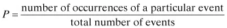
The definitions of the preceding section imply that the voltage level in each time interval, τ, is independent of the voltage level in other time intervals. However, one very simple example where this is not the case is the transmission of the English language. It is known in the English language that the letter e is much more likely to appear than the letter z. It is almost certain that the letter q will be followed by the letter u. So in transmitting a typical message in English, less information is being actually sent than there would be if each letter in the alphabet were equally likely to occur. A way to express this situation is in terms of probability. The total number of signal combinations that could occur in a message T seconds long if the value in each interval is independent of the others is nT/τ. On average, every possible message T seconds long would have a probability of occurrence of 1/nT/τ.
The probability takes the form
(1.4)
Information can be measured in terms of probability. The probability is P = 1/n if there are n possible events specified as one of n voltage levels, and each of these events is equally likely. For any one event, the information transmitted is written H1 = −P log2P. For m intervals, each τ seconds long, there will be m times more information. For m intervals, the information written in terms of probability is
(1.5)
Consider a binary system, where a number 0 occurs with a probability of p and the number 1 occurs with a probability of q. Knowing that p + q = 1, the information content...
Table of contents
Cover
Title page
Copyright page
Dedication
Preface to the Second Edition
Preface to the First Edition
CHAPTER ONE Information Transfer Technology
CHAPTER TWO Resistors, Capacitors, and Inductors
CHAPTER THREE Impedance Matching
CHAPTER FOUR Multiport Circuit Parameters and Transmission Lines
CHAPTER FIVE Filter Design and Approximation
CHAPTER SIX Transmission Line Transformers
CHAPTER SEVEN Noise in RF Amplifiers
CHAPTER EIGHT Class A Amplifiers
CHAPTER NINE RF Power Amplifiers
CHAPTER TEN Oscillators and Harmonic Generators
CHAPTER ELEVEN RF Mixers
CHAPTER TWELVE Phase-Lock Loops
APPENDIX A Example of a Solenoid Design
APPENDIX B Analytical Spiral Inductor Model
APPENDIX C Double-Tuned Matching Circuit Example
APPENDIX D Two-Port Parameter Conversion
APPENDIX E Termination of a Transistor Port with a Load
APPENDIX F Transistor and Amplifier Formulas
APPENDIX G Transformed Frequency-Domain Measurements Using SPICE
APPENDIX H Single-Tone Intermodulation Distortion Suppression for Double-Balanced Mixers
Index
Frequently asked questions
Yes, you can cancel anytime from the Subscription tab in your account settings on the Perlego website. Your subscription will stay active until the end of your current billing period. Learn how to cancel your subscription
No, books cannot be downloaded as external files, such as PDFs, for use outside of Perlego. However, you can download books within the Perlego app for offline reading on mobile or tablet. Learn how to download books offline
Perlego offers two plans: Essential and Complete
Essential is ideal for learners and professionals who enjoy exploring a wide range of subjects. Access the Essential Library with 800,000+ trusted titles and best-sellers across business, personal growth, and the humanities. Includes unlimited reading time and Standard Read Aloud voice.
Complete: Perfect for advanced learners and researchers needing full, unrestricted access. Unlock 1.5M+ books across hundreds of subjects, including academic and specialized titles. The Complete Plan also includes advanced features like Premium Read Aloud and Research Assistant.
Both plans are available with monthly, semester, or annual billing cycles.
We are an online textbook subscription service, where you can get access to an entire online library for less than the price of a single book per month. With over 1.5 million books across 990+ topics, we’ve got you covered! Learn about our mission
Look out for the read-aloud symbol on your next book to see if you can listen to it. The read-aloud tool reads text aloud for you, highlighting the text as it is being read. You can pause it, speed it up and slow it down. Learn more about Read Aloud
Yes! You can use the Perlego app on both iOS and Android devices to read anytime, anywhere — even offline. Perfect for commutes or when you’re on the go. Please note we cannot support devices running on iOS 13 and Android 7 or earlier. Learn more about using the app
Yes, you can access Radio Frequency Circuit Design by W. Alan Davis in PDF and/or ePUB format, as well as other popular books in Technology & Engineering & Electrical Engineering & Telecommunications. We have over 1.5 million books available in our catalogue for you to explore.