- English
- ePUB (mobile friendly)
- Available on iOS & Android
eBook - ePub
About this book
FPGA Prototyping Using Verilog Examples will provide you with a hands-on introduction to Verilog synthesis and FPGA programming through a "learn by doing" approach. By following the clear, easy-to-understand templates for code development and the numerous practical examples, you can quickly develop and simulate a sophisticated digital circuit, realize it on a prototyping device, and verify the operation of its physical implementation. This introductory text that will provide you with a solid foundation, instill confidence with rigorous examples for complex systems and prepare you for future development tasks.
Trusted by 375,005 students
Access to over 1.5 million titles for a fair monthly price.
Study more efficiently using our study tools.
Information
PART I
BASIC DIGITAL CIRCUITS
CHAPTER 1
GATE-LEVEL COMBINATIONAL CIRCUIT
1.1 INTRODUCTION
Verilog is a hardware description language. It was developed in the mid-1980s and later transferred to the IEEE (Institute of Electrical and Electronics Engineers). The language is formally defined by IEEE Standard 1364. The standard was ratified in 1995 (referred to as Verilog-1995) and revised in 2001 (referred to as Verilog-2001). Many useful enhancements are added in the revised version. We use Verilog-2001 in this book.
Verilog is intended for describing and modeling a digital system at various levels and is an extremely complex language. The focus of this book is on hardware design rather than the language. Instead of covering every aspect of Verilog, we introduce the key Verilog synthesis constructs by examining a collection of examples. Several advanced topics are examined further in Chapter 7 and detailed Verilog coverage may be explored through the sources listed in the bibliographic section at the end of the chapter.
Although the syntax of Verilog is somewhat like that of the C language, its semantics (i.e., “meaning”) is based on concurrent hardware operation and is totally different from the sequential execution of C. The subtlety of some language constructs and certain inherent non-deterministic behavior of Verilog can lead to difficult-to-detect errors and introduce a discrepancy between simulation and synthesis. The coding of this book follows a “better-safe-than-buggy” philosophy. Instead of writing quick and short codes, the focus is on style and constructs that are clear and synthesizable and can accurately describe the desired hardware.
Table 1.1 Truth table of 1-bit equality comparator
input | output |
i0 il | eq |
00 | 1 |
01 | 0 |
10 | 0 |
11 | 1 |
In this chapter, we use a simple comparator to illustrate the skeleton of a Verilog program. The description uses only logic operators and represents a gate-level combinational circuit, which is composed of simple logic gates. In Chapter 3, we cover the remaining Verilog operators and constructs and examine the register-transfer-level combinational circuits, which are composed of intermediate-sized components, such as adders, comparators, and multiplexers.
1.2 GENERAL DESCRIPTION
Consider a 1-bit equality comparator with two inputs, i0 and i1, and an output, eq. The eq signal is asserted when i0 and i1 are equal. The truth table of this circuit is shown in Table 1.1.
Assume that we want to use basic logic gates, which include not, and, or, and xor cells, to implement the circuit. One way to describe the circuit is to use a sum-of-products format. The logic expression is
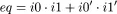
One possible Verilog code is shown in Listing 1.1. We examine the language constructs and statements of this code in the following subsections.
Listing 1.1 Gate-level implementation of a 1-bit comparator
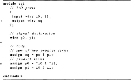
Figure 1.1 Graphical representation of a comparator program.
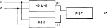
The best way to understand an HDL (hardware description language) program is to think in terms of hardware circuits. This program consists of three portions. The I/O port portion describes the input and output ports of this circuit, which are i0 and i1, and eq, respectively. The signal declaration portion specifies the internal connecting signals, which are p0 and p1. The body portion describes the internal organization of the circuit. There are three continuous assignments in this code. Each can be thought of as a circuit part that performs certain simple logical operations. We examine the language constructs and statements of this code in the next section.
The graphical representation of this program is shown in Figure 1.1. The three continuous assignments constitute the three circuit parts. The connections among these parts are specified implicitly by the signal and port names.
1.3 BASIC LEXICAL ELEMENTS AND DATA TYPES
1.3.1 Lexical elements
Identifier An identifier gives a unique name to an object, such as eql, i0, or p0. It is composed of letters, digits, the underscore character (_), and the dollar sign ($). $ is usually used with a system task or function.
The first character of an identifier must be a letter or underscore. It is a good practice to give an object a descriptive name. For example, mem_addr_en is more meaningful than mae for a memory address enable signal.
Verilog is...
Table of contents
- Cover
- Contents
- Title
- Copyright
- Dedication
- Preface
- Acknowledgement
- PART I BASIC DIGITAL CIRCUITS
- PART II I/O MODULES
- PART III PICOBLAZE MICROCONTROLLLE XILINX SPECIFIC
- Appendix A: Sample Verilog templates
- References
- Topic Index
Frequently asked questions
Yes, you can cancel anytime from the Subscription tab in your account settings on the Perlego website. Your subscription will stay active until the end of your current billing period. Learn how to cancel your subscription
No, books cannot be downloaded as external files, such as PDFs, for use outside of Perlego. However, you can download books within the Perlego app for offline reading on mobile or tablet. Learn how to download books offline
We are an online textbook subscription service, where you can get access to an entire online library for less than the price of a single book per month. With over 1.5 million books across 990+ topics, we’ve got you covered! Learn about our mission
Look out for the read-aloud symbol on your next book to see if you can listen to it. The read-aloud tool reads text aloud for you, highlighting the text as it is being read. You can pause it, speed it up and slow it down. Learn more about Read Aloud
Yes! You can use the Perlego app on both iOS and Android devices to read anytime, anywhere — even offline. Perfect for commutes or when you’re on the go.
Please note we cannot support devices running on iOS 13 and Android 7 or earlier. Learn more about using the app
Please note we cannot support devices running on iOS 13 and Android 7 or earlier. Learn more about using the app
Yes, you can access FPGA Prototyping by Verilog Examples by Pong P. Chu in PDF and/or ePUB format, as well as other popular books in Computer Science & Computer Engineering. We have over 1.5 million books available in our catalogue for you to explore.