![]()
1
Introduction to Mobile Handsets
1.1 Introduction to Telecommunication
The word telecommunication was adapted from the French word télécommunication, where the Greek prefix tele- (τηλε-) means- “far off,” and the Latin word communicare means “to share.” Hence, the term telecommunication signifies communication over a long distance. In ancient times, people used smoke signals, drum beats or semaphore for telecommunication purposes. Today, it is mainly electrical signals that are used for this purpose. Optical signals produced by laser sources are recent additions to this field. Owing to the evolution of major technological advances, today telecommunication is widespread through devices such as the television, radio, telephone, mobile phone and so on. Telecommunication networks carry information signals from one user to another user, who are separated geographically and this entity may be a computer, human being, teleprinter, data terminal, facsimiles machine and so on. The basic purpose of telecommunication is to transfer information from one user to another distant user via a medium. God has given us two beautiful organs: one is an eye to visualize things and other is an ear to listen. So, to the end users, in general information transfer is either by voice or as a real world image. Thus, we need to exchange information through voices, images and also computer data or digital information.
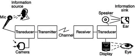
1.1.1 Basic Elements of Telecommunication
The basic elements of a telecommunication system are shown in the Figure 1.1. In telephonic conversation, the party who initiates the call is known as the calling subscriber and the party who is called is known as the called subscriber. They are also known as source and destination, respectively. The user information, such as sound, an image and so on, is first converted into an electrical signal using a transducer, such as a microphone (which converts sound waves into an electrical signal), a video camera (which converts an image into an electrical signal) and so on, which is then transmitted to the distant user via a medium using a transmitter. The distant user receives the signal through the use of a receiver and this is then fed to an appropriate transducer to convert the electrical signal back into the respective information (for example, a speaker is used as a transducer on the receiver side to convert the electrical signal into a sound wave or the LCD display is used to convert the electrical signal into an image).
Before getting into an in-depth discussion, we will first familiarize ourselves with some of the most commonly used terms and mathematical tools for mobile telecommunication system design and analysis. We will learn about some of these as we progress through the various chapters.
1.1.1.1 Signal
The amplitude of a time varying event is described as a signal. Using Fourier’s theory a signal can be decomposed into a combination of pure tones, called sine or cosine waves, at different frequencies. Different sine waves that compose a signal can be plotted as a function of frequency to produce a graph called a frequency spectrum of a signal. The notion of a sinusoid with exponentially varying amplitude can be generalized by using a complex exponential. Based on the nature of the repetition of the signal amplitude with respect to time, the signal can be classified as periodic (repeats with every period) and aperiodic (not a periodic waveform). Also, signals can be either continuous or discrete in nature with respect to time.
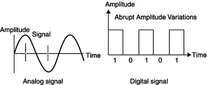
Analog Signal
Analog signals are continuous with time as shown in Figure 1.2. For example, a voice signal is an analog signal. The intensity of the voice causes electric current variations. At the receiving end, the signal is reproduced in the same proportions.
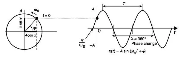
As shown in the Figure 1.3, the signal can be represented in complex cartesian or polar format. Here, T is period of aperiodic signal (T = 1/frequency) and A is the maximum amplitude. ωo is the angular frequency (=2τf) and Φ is the phase at any given instant of time (here at t = 0).
Signals having the same frequency follow the same path (repeat on every period T), but different points on the wave are differentiated by phase (leading or lagging). From the figure it is obvious that one period (T) is 360° of a phase (a complete rotation). Harmonics (2f, 3f, …) are waves having frequencies that are integer multiples of the fundamental frequency. These are harmonically related exponential functions.
Digital Signal
Digital signals are non-continuous with time, for example, discrete. They consist of pulses or digits with discrete levels or values. The value of each pulse width and amplitude level is constant for two distinct types, “1” and “0”, of digital values. Digital signals have two amplitude levels, called nodes and the value of which is specified as one of two possibilities, such as 1 or 0, HIGH or LOW, TRUE or FALSE and so on. In reality, the values are anywhere within specific ranges and we define the values within a given range. A system which uses a digital signal for processing the information is known as a digital system. A digital system has certain advantages over an analog system, as mentioned below.
Advantages – (1) Digital systems are less affected by any noise signal compared with analog signals. Unless the noise exceeds a certain threshold, the information contained in digital signals will remain intact. (2) In an analog system, aging and wear and tear will degrade the information that is stored, but in a digital system, as long as the wear and tear is below a certain level, the information can be recovered perfectly. Thus, it is easier to store and retrieve the data without degradation in a digital system. (3) It provides an easier interface to a computer or other digital devices. Apart from this ease of multiplexing, ease of signaling has made it more popular.
Disadvantages – From their origins, voice and video signals are analog in nature. Hence, we need to convert these analog signals into the digital domain for processing, and after processing again we need to convert them back into the original form to reproduce. This leads to processing overheads and information loss due to conversions.
Digital Signaling Formats
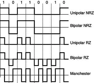
The digital signals are represented in many formats, such as non-return to zero, return to zero and so on, as shown in Figure 1.4. In telecommunication, a non-return-to-zero (NRZ) line code is a binary code in which “1s” are represented by one significant condition and “0s” are represented by the other significant condition, with no other neutral or rest condition. Return-to-zero (RZ) describes a line code used in telecommunications signals in which the signal drops (returns) to zero between each pulse. The NRZ pulses have more energy than an RZ code, but they do not have a rest state, which means a synchronization signal must also be sent alongside the code.
Unipolar Non-Return-to-Zero (NRZ) – Here, symbol “1” is represented by transmitting a pulse of constant amplitude for the entire duration of the bit interval, and symbol “0” is represented by no pulse. This allows for long series without change, which makes synchronization difficult. Unipolar also contains a strong dc component, which causes several problems in the receiver circuits, such as dc offset.
Bipolar Non-Return-to-Zero – Here, pulses of equal positive and negative amplitudes represent symbols “1” and “0.” (for example, ± A volts). This is relatively easy to generate. Because of the positive and negative levels, the average voltage will tend towards zero. So, this helps to reduce the dc component, but causes difficulties for synchronization.
Unipolar Return-to-Zero – Symbol “1” is represented by a positive pulse of amplitude A and half symbol width and symbol “0” is represented by transmitting no pulse.
Bipolar Return-to-Zero – Positive and negative pulses of equal amplitude are used alternatively for symbol “1,” with each pulse having a half-symbol width; no pulse is used for symbol “0.” The “zero” between each bit is a neutral or rest condition. One advantage of this is that the power spectrum of the transmitted signal has no dc components.
Manchester Coding – In the Manchester coding technique, symbol “1” is represented by a positive pulse followed by a negative pulse, with each pulse being of equal amplitude and a duration of half a pulse. The polarities of these pulses are reversed for symbol “0.” An advantage of this coding is that it is easy to recover the original data clock and relatively less dc com...