![]()
Part One
![]()
1
Foundations
1.1 HISTORICAL PERSPECTIVE
In only a few years, Multi-Protocol Label Switching (MPLS) has evolved from an exotic technology to a mainstream tool used by service providers to create revenue-generating services. There is rapid deployment of MPLS-enabled services and active development of new mechanisms and applications for MPLS in the standards bodies. This book aims to describe the fundamental mechanisms used by MPLS and the main service types that MPLS enables, such as Virtual Private Networks (VPNs). We include descriptions of new applications of MPLS that are currently under development.
The history of MPLS and its precursors is described in [Davie Rekhter] and [Doyle Kolon]. The first Internet Engineering Task Force (IETF) MPLS Working Group Meeting took place in April 1997. That working group still exists, and MPLS has grown to the extent that it underpins much of the activity of several other working groups in the IETF, such as Layer 3 VPN (l3vpn), Layer 2 VPN (l2vpn), Pseudo Wire Emulation Edge-to-Edge (pwe3) and Common Control and Measurement Plane (ccamp). Part of the original MPLS problem statement [MPLS97] from the first MPLS working group meeting is shown below. It contains four items that the group aimed to address through the development of MPLS. It is interesting to examine these to see which items are still relevant today:
1. Scalability of network layer routing. Using labels as a means to aggregate forwarding information, while working in the presence of routing hierarchies.
Layer 3 VPNs have proved to be a good example of aggregation of forwarding information. As described in Chapter 7 of this book, edge routers need to contain routing information pertaining to each VPN that they service, but the core routers do not. Thus, assuming that any edge router services only a subset of the VPNs pertaining to the network, no router in the network needs to hold the entire set of routes present in the network.
2. Greater flexibility in delivering routing services. Using labels to identify particular traffic which are to receive special services, e.g. QoS. Using labels to provide forwarding along an explicit path different from the one constructed by destination-based forwarding.
MPLS has the ability to identify particular traffic flows which must receive special services such as Quality-of-Service (QoS). It also has traffic engineering properties that allow it to provide forwarding along a particular explicit path. These two properties are combined in DiffServ Aware Traffic Engineering, which is described in more detail in Chapter 4 of this book.
3. Increased performance. Using the label-swapping paradigm to optimize network performance.
Because modern routers perform packet forwarding in hardware, the forwarding rates for IP and MPLS packets are similar. However, ‘optimizing network performance’ implies a wider context than simply the performance of individual nodes. Certainly MPLS has helped in this wider context, e.g. through the use of traffic engineering to avoid congestion and the use of fast reroute to reduce the interruption to traffic when a link in the network fails.
4. Simplify integration of routers with cell switching based technologies: a) making cell switches behave as peers to routers (thus reducing the number of routing peers that a router has to maintain), b) by making information about physical topology available to Network Layer routing procedures, and c) by employing common addressing, routing, and management procedures.
When this item in the problem statement was written, many networks had a core of asynchronous transfer mode (ATM) switches surrounded by routers. The routers were typically fully meshed with ATM connections. This overlay model was proving difficult to scale because the number of routing adjacencies required grew as the square of the number of routers involved; hence there was a requirement to make the ATM switches act as peers to the routers. It is interesting to note that the situation has now been turned inside out: now many networks have an MPLS-based core, and service providers are migrating ATM services to this core network by interconnecting ATM switches with Layer 2 connections over the MPLS core! This has the problem that the number of adjacencies between ATM switches grows as the square of the number of ATM switches involved. Hence, currently there is work on making ATM switches behave as peers to routers [MPLS ALLI]. This is to avoid having a full mesh of adjacencies between ATM switches rather than to avoid having a full mesh of adjacencies between routers, as stated in the problem statement. The concept expressed in the problem statement of using MPLS as a control plane for multiple technologies has manifested itself in Generalized MPLS (GMPLS). In GMPLS, a common control plane covers a wide range of network devices, such as routers, ATM switches, SONET/SDH equipment and optical cross-connects [RFC3945].
In summary, much of the original problem statement is still relevant today. Many of the mechanisms of MPLS described in Part 1 of this book were developed to address the items listed above, to the benefit of the MPLS applications discussed in Part 2 of this book.
1.2 CURRENT TRENDS
At the time of writing this book, the most widely deployed customer-visible MPLS service is the Layer 3 VPN (also known as an IP VPN or 2547bis VPN, after the IETF document describing them). MPLS is also used in some networks as an infrastructure tool to provide traffic engineering and fast-reroute capabilities. Another rapidly growing application is point-to-point Layer 2 transport, either as means of carrying a customer's Ethernet traffic across the wide area or as a component of ATM or Frame Relay Service emulation. Finally, Virtual Private LAN Service (VPLS) offerings, in which the service provider gives the impression to the customer that their sites are attached to the same Local Area Network (LAN), are also becoming available.
Many service providers are investigating the possibility of using an MPLS-based network to provide a common platform for a wide range of services that are currently typically delivered over multiple distinct networks. Such a multiservice network might carry Public Switched Telephone Network (PSTN) traffic, public Internet and private IP data services, Layer 2 ATM and Frame Relay services, Broadcast TV and TDM traffic. This offers capital and operational cost savings to the network operators by allowing them to operate a single network rather than a separate network for each service type. A key aim of this book is to show how MPLS can provide the necessary mechanisms for this network convergence, e.g. through the use of DiffServ Aware Traffic Engineering (TE), which allows the MPLS network to provide connection-orientated characteristics to particular traffic flows.
1.3 MPLS MECHANISMS
This section gives an overview of the mechanisms underpinning MPLS. Readers who are familiar with these may wish to skip this section.
A fundamental property of an MPLS network is that it can be used to tunnel multiple traffic types through the core of the network. Tunneling is a powerful tool because only the routers at the ingress and the egress of the tunnel need to understand the ‘context’ of the underlying traffic carried over the tunnel (e.g. the protocol that the traffic belongs to and the reachability information required to route and forward it in its native form). This detail is hidden from routers in the core of the network. As a consequence, core devices only need to carry sufficient state to enable them to switch MPLS-encapsulated packets without regard to their underlying content. Besides these aggregation properties, which apply to tunnels in general, MPLS tunnels have the following particular properties:
1. Traffic can be explicitly routed, depending on which signaling protocol is used.
2. Recursion is provided for; hence tunnels can exist within tunnels.
3. There is protection against data spoofing, as the only place where data can be injected into an MPLS tunnel is at the head end of that tunnel. In contrast, data can be injected into an IP tunnel from any source that has connectivity to the network that carries the tunnel.
4. The encapsulation overhead is relatively low (4 bytes per MPLS header).
An MPLS network consists of edge devices known as Label Edge Routers (LERs) or Provider Edge (PE) routers and core routers known as Label Switching Routers (LSRs) or Provider (P) routers. A mesh of unidirectional tunnels, known as Label Switched Paths (LSPs) is built between the LERs in order that a packet entering the network at the ingress LER can be transported to the appropriate egress LER. When packets enter a network, the ingress router determines which Forwarding Equivalence Class (FEC) the packets belong to. Packets that are to be forwarded to the same egress point in the network along the same path and with the same forwarding treatment along that path are said to belong to the same FEC. Packets belonging to the same FEC are forwarded with the same MPLS label. In a simple case, packets whose destination addresses correspond to the same Border Gateway Protocol (BGP) next-hop are regarded by the ingress router as belonging to the same FEC. In other cases, there may be a more granular assignment of packets to FECs. For example, in DiffServ Aware TE, each egress point in the network may have multiple FECs, each belonging to a different traffic class.
It is the role of the ingress LER to determine the appropriate egress LER and LSP to that egress LER associated with the FEC. MPLS has the property that multiple traffic types can be multiplexed on to a single LSP. Therefore, if desired by the network operator, a single LSP can be used to carry all the traffic (e.g. L3VPN, public IP and Layer 2) between a particular ingress LER and a particular egress LER. Transit routers along the path of the LSP make their forwarding decision on the basis of a fixed-format MPLS header, and hence do not need to store ‘routes’ (L3VPN routes, external IP routes, Layer 2 forwarding information) pertaining to the underlying tunneled packets. This is an important scaling property, as otherwise each of the core routers would have to carry routing information equivalent to the sum of the routing information carried by all the edge routers in the network.
The following sections describe the fundamental forwarding plane and control plane mechanisms underpinning MPLS.
1.3.1 Forwarding plane mechanisms
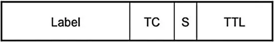
Data carried over an MPLS-capable network has one or more MPLS headers applied in order to transport it across the network. The MPLS header structure is shown in Figure 1.1. It contains the following fields:
1. A 20-bit label value. MPLS packets are forwarded on the basis of this field. This value is used as an index into the MPLS forwarding table.
2. Traffic Class (TC) field (3 bits). Previously known as the EXP bits,1 convey the Class of Service to be applied to the packet. For example, LSRs and LERs can use these bits to determine the queue into which the packet should be placed. Note that in some cases, as described later in this chapter, the MPLS label value also determines the queuing behavior applied to the packet.
3. Bottom of stack bit (S-bit). As described later in this chapter, MPLS headers can be stacked. The S-bit is set on the header of the MPLS packet at the bottom of the stack.
4. Time-to-live (TTL) field. This is used to avoid forwarding loops and can also be used for path-tracing. The value is decremented at each hop and the packet is discarded should the value reach zero.
Packets arriving into the network have one or more MPLS headers applied by the ingress LER. The ingress LER identifies the egress LER to which the packet must be sent and the corresponding LSP. The label value used corresponds to the LSP on to which the packet is placed. The next router performs a lookup of that label and determines the output label that must be used for the next leg of the LSP. The lookup operation on a P router involves reading the incoming label; this yields a new label value to use and the output interface(s) on which the packet should be forwarded. In this way, through this label-swapping paradigm, the packet is conveyed along the LSP from the ingress to the egress LER.
In some simple cases, the use of a single MPLS label is sufficient, e.g. when transporting public IP traffic across a network. In this case, once the packet arrives at the egress LER, the LER performs a normal IP lookup in order to determine which egress link to use. Usually a scheme called Penultimate Hop Popping (PHP) is used. In this scheme, the LSR befor...