![]()
1
Calculation of the cross-sectional areas of circuit live conductors
The first stage in designing an installation after having carried out the assessment of general characteristics demanded in Part 3 of BS 7671 is the choice of the type of cable and the method of installation of that cable for each circuit. In some cases these choices are closely interrelated, e.g. non-sheathed cables are required to be enclosed in conduit, duct, ducting or trunking (Regulation 521.10.1).
Where there are several options open to the installation designer from purely technical considerations, the final choice will depend on commercial aspects or the designer’s (or client’s) personal preferences. Here it is assumed that the designer, after having taken into account the relevant external influences to which the circuit concerned is expected to be subjected, has already decided on the type of cable and the installation method to use. The appropriate table of current-carrying capacity, in Appendix 4 of BS 7671, and the appropriate column within that table are therefore known.
To determine the minimum conductor cross-sectional area of the live conductors of a particular circuit that can be tolerated the designer must:
(a) Establish what is the expected ambient temperature (ta °C). This gives the relevant value of Ca. Note that more than one value of ta°C may be encountered in some installations. Where there is more than one value the designer may opt to base all his calculations on the highest value or, alternatively, base his calculations for a particular part of the installation on the value of ta°C pertinent to that part.
(b) Decide whether the circuit is to be run singly or be bunched or grouped with other circuits and, if the latter, how many other circuits. The decision taken gives the relevant value of Cg.
(c) Decide whether the circuit is likely to be totally surrounded by thermally insulating material for any part of its length (Regulation 523.7). If the length surrounded by thermal insulation is more than 0.5 m, Ci is taken to be 0.5. For shorter lengths surroundedby thermal insulation the factors given in Table 52.2 are applied.
(d) Determine the design current (Ib) of the circuit, taking into account diversity where appropriate (Regulation 311.1), and any special characteristics of the load, e.g. motors subject to frequent stopping and starting (Regulation 552.1.1).
(e) Choose the type and nominal current rating (In) of the associated overcurrent protective device. For all cases In must be equal to or greater than Ib. Remember that overcurrent protective devices must comply with Chapter 43 of BS 7671 as regards their breaking capacity, but for the present let it be assumed the chosen devices do so comply.
(f) Establish whether it is intended the overcurrent protective device is to give:
(i) overload protection only, or
(ii) short circuit protection only, or
(iii) overload and short circuit protection.
The intended function of the overcurrent protective device not only determines whether Ib or In is used as the basis for calculating the minimum cross-sectional area of the live conductors, but also influences the value of Ca that is to be used in the calculations.
(g) Establish the maximum voltage drop that can be tolerated, (h) Estimate the route length of the circuit.
If the cable circuit is to be buried direct in the ground or in buried ducts there are further factors the designer must consider. These factors include:
(a) The thermal resistivity of the ground. The tabulated ratings given for buried cables in BS 7671 are for cables buried ‘in or around buildings’. These ratings assume that the cables are buried in dry made-up ground that is likely to contain rubble, clinker and similar materials having poor thermal properties. Because of this the ratings are based on a soil thermal resistivity of 2.5 K.m/W. This is considerably higher than the accepted value of 1.2 K.m/W for the natural soil in the UK, see BS IEC 60827–3-1. Tabulated ratings for buried cables based on a thermal resistivity of 1.2 K.m/W are given in ERA Reports 69—30 Parts III and IV as well as being provided by some UK cable suppliers. The thermal properties of the soil determine the value of Cs selected from Table 4B3 of BS 7671.
(b) The depth of burial of the cables or ducts. The deeper a circuit is buried the lower its current rating. The tabulated ratings given in BS 7671 are for a depth of burial of 0.8 m and no factors are given for different depths of burial. Derating factors for different depths, Cb, may be obtained from the cable supplier or taken from ERA Report 69—30 Part III or IV. However the ratings in many manufacturers’ data and in the ERA reports are for a depth of burial of 0.5 m. Thus the factors for different depths of burial would have to be manipulated before being applied to ratings based on a depth of 0.8 m.
(c) Ground ambient temperature. The tabulated ratings for buried cables given in BS 7671 are based on a ground ambient temperature of 20°C. This is applicable under buildings, but the designer should be aware that the accepted ground ambient temperature for general conditions in the UK is 15°C, see BS IEC 60287–3-1.
(d) Overload protection of buried cables. The requirement of Regulation 433.1.1 (iii) is applicable to circuits where the tabulated current ratings are based on an ambient temperature of 30°C. To achieve overload protection for a buried cable circuit the 1.45 factor given in Regulation 433.1.1 (iii) should be reduced to 1.3. In BS 7671 this is achieved by applying a factor of 0.9 to the current-carrying capacity, Iz, as required by Regulation 433.1.4. As an alternative the overload protective device should be selected such that I2 < 1.3Iz.
It cannot be emphasized too strongly that unless all the foregoing items are available it is not possible to design any circuit.
The general method for the determination of the minimum conductor cross-sectional areas that can be tolerated now described does not apply to cables installed in enclosed trenches. These are considered later in this chapter. The general method is as follows:
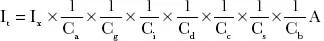
First calculate the current It where:
Table 1.1 indicates when Ix = Ib and when Ix = In. Table 1.1 also indicates from which tables in Appendix 4 of BS 7671 the appropriate values of Ca and Gg are found and it gives the values of Cd to use. For all buried cable circuits, Cc = 0.9 where the current, I2, causing effective operation of the protective device is 1.45 times the rated current, In, of the protective device. Where I2≥ 1.3 × In, Cc = 1. The value of Cs for a buried circuit is selected from Table 4B3.
Ci (when applicable) is, in the absence of more precise information, taken to be 0.5 and the calculation is then based on the tabulated current-carrying capacity for Reference Method B, i.e. for cables clipped direct to a surface and open. Note that even when the cable concerned is installed in thermal insulation for comparatively short lengths (up to 400mm), Regulation 523.7 specifies derating factors varying from 0.89 to 0.55.
Having calculated It, inspect the appropriate table of current-carrying capacity in Appendix 4 and the appropriate column in that table to find that conductor cross-sectional area having an actual tabulated current-carrying capacity (Ita) equal to or greater than the calculated It.
Note that in the following examples the circuit lengths are not given and therefore the voltage drops are not calculable. The examples are concerned solely with the determination of conductor cross-sectional areas for compliance with the requirements in BS 7671 regarding the thermal capability of cables under normal load conditions and, where appropriate, under overload conditions.
Remember that Regulation 435.1 allows the designer to assume that, if the overcurrent protective device is intended to provide both overload and short circuit protection, there is no...