This book describes the application of polarimetric synthetic aperture radar to earth remote sensing based on research at the NASA Jet Propulsion Laboratory (JPL). This book synthesizes all current research to provide practical information for both the newcomer and the expert in radar polarimetry. The text offers a concise description of the mathematical fundamentals illustrated with many examples using SAR data, with a main focus on remote sensing of the earth.
The book begins with basics of synthetic aperture radar to provide the basis for understanding how polarimetric SAR images are formed and gives an introduction to the fundamentals of radar polarimetry. It goes on to discuss more advanced polarimetric concepts that allow one to infer more information about the terrain being imaged. In order to analyze data quantitatively, the signals must be calibrated carefully, which the book addresses in a chapter summarizing the basic calibration algorithms. The book concludes with examples of applying polarimetric analysis to scattering from rough surfaces, to infer soil moisture from radar signals.
Trusted by 375,005 students
Access to over 1.5 million titles for a fair monthly price.
The word “radar” is an acronym for “radio detection and ranging.” A radar measures the distance, or range, to an object by transmitting an electromagnetic signal to and receiving an echo reflected from the object. Since electromagnetic waves propagate at the speed of light, one only has to measure the time it takes the radar signal to propagate to the object and back to calculate the range to the object. The total distance traveled by the signal is twice the distance between the radar and the object, since the signal travels from the radar to the object and then back from the object to the radar after reflection. Therefore, once we measured the propagation time (t), we can easily calculate the range (R) as
(1-1)
where c is the speed of light in a vacuum. The factor ½ accounts for the fact that the radar signal actually traveled twice the distance measured: first from the radar to the object and then from the object to the radar. If the electric property of the propagation medium is different from that of the vacuum, the actual propagation velocity has to be estimated for advanced radar techniques, such as synthetic aperture radar (SAR) interferometry.
Radars provide their own signals to detect the presence of objects. Therefore, radars are known as active, remote-sensing instruments. Because radars provide their own signal, they can operate during day or night. In addition, radar signals typically penetrate clouds and rain, which means that radar images can be acquired not only during day or night but also under (almost) all weather conditions. For these reasons, radars are often referred to as all-weather instruments. Imaging, remote-sensing radars, such as SAR, produce high-resolution (from submeter to a few tens of meters) images of surfaces. The geophysical information can be derived from these high-resolution images by using proper postprocessing techniques.
This book focuses on a specific class of implementation of synthetic aperture radar with particular emphasis on the use of polarization to infer the geophysical properties of the scene. As mentioned above, SAR is a way to achieve high-resolution images using radio waves. We shall first describe the basics of radar imaging. This shall be followed by a description of the synthetic aperture principle. Finally, we shall discuss some advanced SAR implementations, such as SAR polarimetry and polarimetric SAR interferometry.
1.1 BASIC PRINCIPLES OF RADAR IMAGING
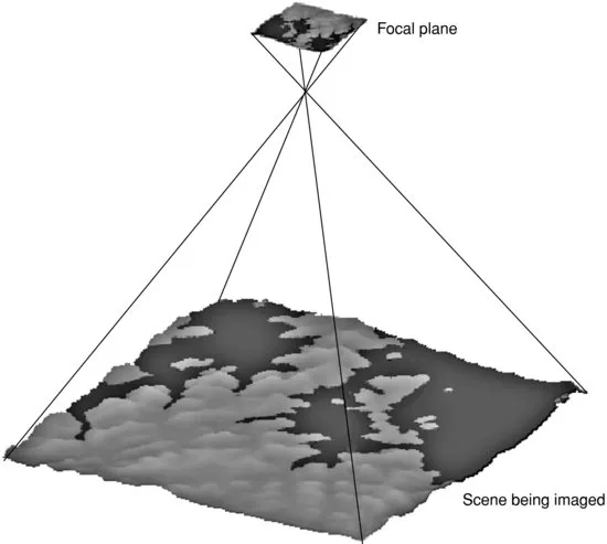
Imaging radars generate surface images that are at first glance very similar to the more familiar images produced by instruments that operate in the visible or infrared parts of the electromagnetic spectrum. However, the principle behind the image generation is fundamentally different in the two cases. Visible and infrared sensors use a lens or mirror system to project the radiation from the scene on a “two-dimensional array of detectors,” which could be an electronic array or, in earlier remote-sensing instruments, a film using chemical processes. The two-dimensionality can also be achieved by using scanning systems or by moving a single line array of detectors. This imaging approach—an approach with which we are all familiar from taking photographs with a camera—conserves the relative angular relationships between objects in the scene and their images in the focal plane, as shown in Figure 1-1. Because of this conservation of angular relationships, the resolution of the images depends on how far away the camera is from the scene it is imaging. The closer the camera, the higher the resolution and the smaller the details that can be recognized in the images. As the camera moves further away from the scene, the resolution degrades and only larger objects can be discerned in the image.
Figure 1-1 Passive imaging systems conserve the angular relationships between objects in the scene and their images in the focal plane of the instrument
Imaging radars use a quite different mechanism to generate images, with the result that the image characteristics are also quite different from those of visible and infrared images. There are two different mechanisms by which radars can be used to produce images; the two types of radars are broadly classified as real aperture and synthetic aperture radars. We shall discuss the differences between these two types in more detail later in this chapter.
Radar images are typically acquired in strips as the satellite or aircraft carrying the radar system moves along its flight path. These strips are often referred to as swaths or tracks. To separate objects in the cross-track direction and the along-track direction within a radar image, two different methods must be implemented. The cross-track direction, also known as the range direction in radar imaging, is the direction perpendicular to the direction in which the imaging platform is moving. In this direction, radar echoes are separated using the time delay between the echoes that are backscattered from the different surface elements. This is true for both real aperture and synthetic aperture radar imagers. The along-track direction, also known as the azimuth direction, is the direction parallel to the movement of the imaging platform. The angular size (in the case of the real aperture radar) or the Doppler history (in the case of the synthetic aperture radar) is used to separate surface pixels in the along-track dimension in the radar images. As we will see later, only the azimuth imaging mechanism of real aperture radars is similar to that of regular cameras. Using the time delay and Doppler history results, SAR images have resolutions that are independent of how far away the radar is from the scene it is imaging. This fundamental advantage enables high-resolution, spaceborne SAR without requiring an extremely large antenna.
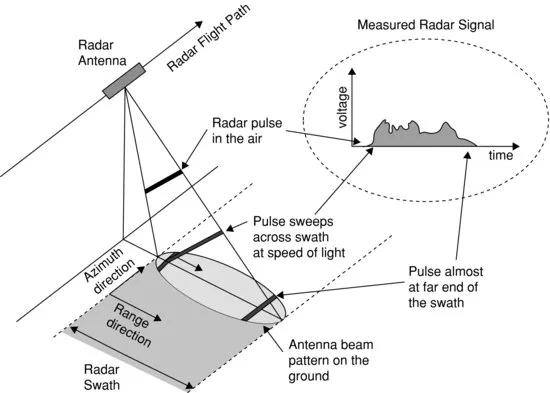
Another difference between images acquired by cameras operating in the visible and near-infrared part of the electromagnetic spectrum and radar images is the way in which they are acquired. Cameras typically look straight down, or at least have no fundamental limitation that prevents them from taking pictures looking straight down from the spacecraft or aircraft. Not so for imaging radars. To avoid so-called ambiguities, which we will discuss in more detail later, the imaging radar sensor has to use an antenna that illuminates the surface to one side of the flight track. Usually, the antenna has a fan beam that illuminates a highly elongated, elliptically shaped area on the surface, as shown in Figure 1-2. The illuminated area across track generally defines the image swath.
Figure 1-2 Imaging geometry for a side-looking radar system
Within the illumination beam, the radar sensor transmits a very short effective pulse of electromagnetic energy. Echoes from surface points farther away along the cross-track coordinate will be received at proportionally later times (see Figure 1-2). Thus, by dividing the receive time in increments of equal time bins, the surface can be subdivided into a series of range bins. The width in the along-track direction of each range bin is equal to the antenna footprint along the track xa. As the platform moves, the sets of range bins are covered sequentially, thereby allowing strip mapping of the surface line by line. This is comparable to strip mapping with a so-called push broom imaging system using a line array in the visible and infrared part of the electromagnetic spectrum. The brightness associated with each...
CHAPTER 5: APPLICATIONS: MEASUREMENT OF SURFACE SOIL MOISTURE
APPENDIX A: TILTED SMALL-PERTURBATION MODEL DETAILS
APPENDIX B: BISTATIC SCATTERING MATRIX OF A CYLINDER WITH ARBITRARY ORIENTATION
APPENDIX C: NOMENCLATURE
Plates
Index
Frequently asked questions
Yes, you can cancel anytime from the Subscription tab in your account settings on the Perlego website. Your subscription will stay active until the end of your current billing period. Learn how to cancel your subscription
No, books cannot be downloaded as external files, such as PDFs, for use outside of Perlego. However, you can download books within the Perlego app for offline reading on mobile or tablet. Learn how to download books offline
Perlego offers two plans: Essential and Complete
Essential is ideal for learners and professionals who enjoy exploring a wide range of subjects. Access the Essential Library with 800,000+ trusted titles and best-sellers across business, personal growth, and the humanities. Includes unlimited reading time and Standard Read Aloud voice.
Complete: Perfect for advanced learners and researchers needing full, unrestricted access. Unlock 1.5M+ books across hundreds of subjects, including academic and specialized titles. The Complete Plan also includes advanced features like Premium Read Aloud and Research Assistant.
Both plans are available with monthly, semester, or annual billing cycles.
We are an online textbook subscription service, where you can get access to an entire online library for less than the price of a single book per month. With over 1.5 million books across 990+ topics, we’ve got you covered! Learn about our mission
Look out for the read-aloud symbol on your next book to see if you can listen to it. The read-aloud tool reads text aloud for you, highlighting the text as it is being read. You can pause it, speed it up and slow it down. Learn more about Read Aloud
Yes! You can use the Perlego app on both iOS and Android devices to read anytime, anywhere — even offline. Perfect for commutes or when you’re on the go. Please note we cannot support devices running on iOS 13 and Android 7 or earlier. Learn more about using the app
Yes, you can access Synthetic Aperture Radar Polarimetry by Jakob J. van Zyl in PDF and/or ePUB format, as well as other popular books in Tecnología e ingeniería & Ingeniería civil. We have over 1.5 million books available in our catalogue for you to explore.