![]()
1
INTRODUCTION
John Thornton and Kao-Cheng Huang
The topic of lens antennas was widely investigated during the early development of microwave antennas and was influenced by the extensive body of existing work from optics. Subsequently, interest declined somewhat as lens antennas were overtaken by reflectors for high efficiency, large aperture antennas; and by arrays for shaped-beam, multi-beam, and scanning antennas. Quite recently, as research interest has expanded into the use of millimeter wave and sub-millimeter wave frequency bands, lens antennas have again attracted developers’ attention.
This chapter is organized as nine sections to introduce the basics of lens antennas. Section 1.1 gives an overview of lens antennas, including its advantages, disadvantages, and the materials encountered. This is followed by a discussion of antenna feeds at Section 1.2. Then Section 1.3 introduces the fundamentals of the Luneburg lens (a topic to which Chapters 6 and 7 are dedicated). Section 1.4 introduces quasi-optics and Section 1.5 treats design rules. A discussion of metamaterials for lens antennas makes up Section 1.6 and then the planar lens array, which is a relative of the reflect-array antenna, follows in Section 1.7. Applications are proposed in Section 1.8 and measurement techniques and anechoic chambers discussed in the final section.
1.1 LENS ANTENNAS: AN OVERVIEW
The use of dielectric lenses in microwave applications seems to date back to the early days of experiments associated with the verification of the optical properties of electromagnetic waves at 60 GHz [1]. However, it was not until World War II that lenses gained interest as antenna elements. Even then they were not widely used because of their bulky size at rather low frequencies.
Nowadays there is a renewed interest in dielectric lenses, not least because of the rapidly growing number of applications for millimeter waves where lens physical dimensions have acceptable sizes. Besides, very low loss dielectric materials are available, and present-day numerically controlled machines enable low-cost fabrication of quite sophisticated lenses made with very good tolerances.
In one of the earliest dielectric lens antenna applications, a homogeneous lens was designed to produce a wide-angle scanning lobe [2]. Also, homogeneous lenses have been used as phase front correctors for horns. The lens is often mounted as a cap on a hollow metallic horn [3]. In this configuration the lens surfaces on both sides can be used to design for two simultaneous conditions. In addition, lenses may be designed to further control the taper of the field distribution at the lens aperture [4] or to shape the amplitude of the output beam in special applications [5].
The aperture of a solid dielectric horn can be shaped into a lens to modify or improve some radiation characteristics [6]. For instance, the aperture efficiency of a solid dielectric horn may be improved by correcting the aperture phase error. Alternatively we may use a lens to shape the amplitude of the output beam or to improve the cross-polarization performance, but because there is only the one lens surface to be varied, only one of these design targets might be made optimum.
1.1.1 The Microwave Lens
In optics, a lens refracts light while a mirror reflects light. Concave mirrors cause light to reflect and create a focal point. In contrast, lenses work the opposite way: convex lenses focus the light by refraction. When light hits a convex lens, this results in focusing since the light is all refracted toward a line running through the center of the lens (i.e., the optical axis). Save for this difference, convex lens antennas work in an analogous fashion to concave reflector antennas. All rays between wavefronts (or phase fronts) have equal optical path lengths when traveling through a lens. Fresnel’s equations, which are based on Snell’s law with some additional polarization effects, can be applied to the lens surfaces.
In general, lenses collimate incident divergent energy to prevent it from spreading in undesired directions. On the other hand, lenses collimate a spherical or cylindrical wavefront produced respectively by a point or line source feed into an outgoing planar or linear wavefront. In practice, however, complex feeds or a multiplicity of feeds can be accommodated since performance does not deteriorate too rapidly with small off-axis feed displacement.
There are two main design concepts used to reach different goals.
1. Conventional (e.g., hyperbolical, bi-hyperbolical, elliptical, hemispherical) or shaped lens antennas are used simply for collimating the energy radiated from a feed.
2. In the case of shaped designs, more complex surfaces are chosen for shaping the beam to produce a required radiation pattern, or for cylindrical and spherical lenses for beam scanning with either single or multiple feeds.
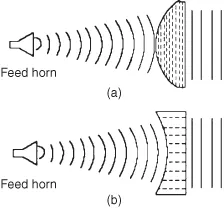
Lenses can also be placed into one or other of the categories of slow wave and fast wave lenses (Fig. 1.1). The terms relate to the phase velocity in the lens medium. The slow-wave lens type is illustrated in Figure 1.1a. Here, the electrical path length is increased by the medium of the lens, hence the wave is retarded.
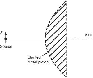
The most common type is the dielectric lens but another example is the H-plane metal-plate lens (Fig. 1.2). (The H-plane is that containing the magnetic field vector and the also the direction of maximum radiation, or main lobe boresight. The magnetizing field or H-plane lies at a right angle to the electric or E-plane.)
Figure 1.1b shows the fast-wave lens type where the electrical path length is effectively made shorter by the lens medium, so the wave is advanced. E-plane metal-plate lenses are of the fast-wave type. (The E-plane is that containing the electric field vector and also the direction of maximum radiation. The E-plane and H-plane are orthogonal to each other and determine the polarization sense of a radio wave.)
In terms of materials, dielectric lenses may be divided into two distinct types:
1. Lenses made of conventional dielectrics, such as Lucite® or polystyrene.
2. Lenses made of artificial dielectrics such as those loaded by ceramic or metallic particles.
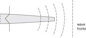
Lens antennas tend to be directive rather than omnidirectional i.e. they usually exhibit a single, distinct radiation lobe in one direction. In this case, they might be thought of as “end-fire” radiators. With this in mind, a dielectric rod, as shown in Figure 1.3, is a good example. Because the rod is usually made from polystyrene, it is called a polyrod. A polyrod acts as a kind of imperfect or leaky waveguide for electromagnetic waves. As energy leaks from the surface of the rod it is manifested as radiation. This tendency to radiate is deliberate, and the rod’s dimensions and shape are tailored to control the radiation properties which are discussed in proper detail in Chapter 3.
In contrast to polyrod antennas, most lens dimensions are much larger than the wavelength, and design is based on the quasi optics (QO) computations. Snell’s refraction law and a path length condition (or eventually an energy conservation condition) are then used to define the lens surface in the limit as the wavelength tends to zero. Depending on the lens shape, diffraction effects may give rise to discrepancies in the final pattern. While these comments really concern axis-symmetric lenses, on the other hand, literature on arbitrary shaped dielectric lenses and three-dimensional amplitude shaping dielectric lens is also available [5].
1.1.2 Advantages of Lens Antennas
Lenses are an effective antenna solution where beam shaping, sidelobe suppression, and beam agility (or steering in space) can be achieved simultaneously from a compact assembly. Dielectric lenses may also brin...