![]()
1
Introduction
1.1 Network Architecture
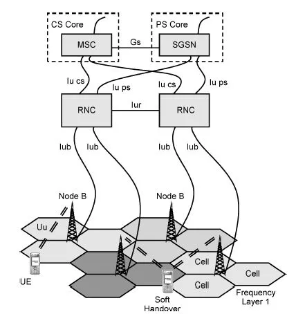
- The RAN includes RNC, Node B and UE. RNC are connected to Node B using the Iub interface. Neighbouring RNC are connected using the Iur interface. UE are connected to Node B using the Uu interface. The RAN is connected to the CN using the Iu interface.
- Each Node B has a controlling RNC and each UE connection has a serving RNC. The serving RNC provides the Iu connection to the CN. Drift RNC can be used by UE connections in addition to the serving RNC.
The network architecture defines the network elements and the way in which those network elements are interconnected. Figure 1.1 illustrates a section of the network architecture for UMTS. This book focuses upon the Radio Access Network (RAN) rather than the core network. The RAN represents the section of the network which is closest to the end-user and which includes the air-interface.
The RAN includes the Radio Network Controller (RNC), the Node B and the User Equipment (UE). The MSC and SGSN are part of the core network. An example UMTS network could include thirty RNC, ten thousand Node B and five million UE. The UE communicate with the Node B using the air-interface which is known as the Uu interface. The Node B communicates with the RNC using a transmission link known as the Iub interface. The RNC communicates with the core network using a transmission link known as the Iu interface. There is an Iu interface for the Circuit Switched (CS) core network and an Iu interface for the Packet Switched (PS) core network. The capacity of the Iu interface is significantly greater than the capacity of the Iub interface because the Iu has to be capable of supporting a large quantity of Node B whereas the Iub supports only a single Node B. Neighbouring RNC can be connected using the Iur interface. The Iur interface is particularly important for UE which are moving from the coverage area of one RNC to the coverage area of another RNC.
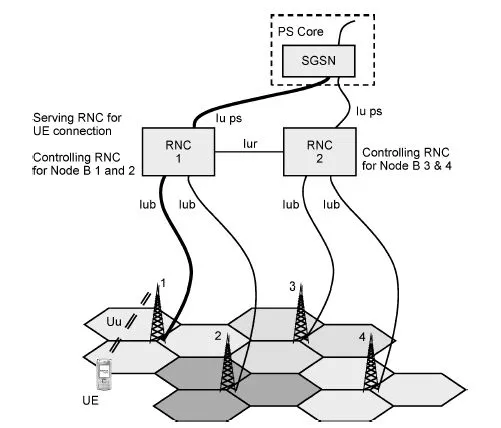
Each Node B has a controlling RNC and each UE connection has a serving RNC. The controlling RNC for a Node B is the RNC which terminates the Iub interface. The serving RNC for a UE connection is the RNC which provides the Iu interface to the core network. Figure 1.2 illustrates an example for a packet switched connection and four Node B.
RNC 1 is the controlling RNC for Node B 1 and 2 whereas RNC 2 is the controlling RNC for Node B3 and 4.The controlling RNC is responsible for managing its Node B. RNC1 is the serving RNC for the packet switched connection because it provides the connection to the PS core network. The serving RNC is responsible for managing its UE connections. As this example illustrates, an RNC can be categorised as both controlling and serving.
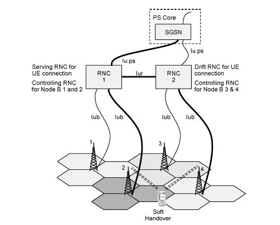
In the case of UE mobility, an RNC can also be categorised as a drift RNC. If a UE starts its connection within the coverage area of RNC 1 then that RNC becomes the serving RNC and will provide the connection to the core network. If the UE subsequently moves into the coverage area of the second RNC then the UE can be simultaneously connected to Node B controlled by both RNC 1 and RNC 2. This represents a special case of soft handover, i.e. inter-RNC soft handover. This scenario is illustrated in Figure 1.3. In general, soft handover allows UE to simultaneously connect to multiple Node B. This is in contrast to hard handover in which case the connection to the first Node B is broken before the connection to the second Node B is established. Soft handover helps to provide seamless mobility to active connections as UE move throughout the network and also helps to improve the RF conditions at cell edge where signal strengths are generally low and cell dominance is poor. In the case of inter-RNC soft handover, the UE is simultaneously connected to multiple RNC. The example illustrated in Figure 1.3 is based upon two RNC but it is possible for UE to be connected to more than two RNC if the RNC coverage boundaries are designed to allow it. In this example, RNC 1 is the serving RNC because it provides the Iu connection to the core network. RNC 2 is a drift RNC because it is participating in the connection, but it is not providing the connection to the core network. A single connection can have only one serving RNC, but can have more than one drift RNC.
Communication between the UE and the serving RNC makes use of the Iur interface when a drift RNC is involved. The Iur interface is an optional transmission link and is not always present. For example, if a network is based upon RNC from two different network vendors then it is possible that those RNC are not completely compatible and the Iur interface is not deployed. If the Iur interface is not present then inter-RNC soft handover is not possible because there is no way to transfer information from the drift RNC to the serving RNC. In this case, the UE has to complete a hard handover when moving into the coverage area of the second RNC. The inter-RNC hard handover procedure allows the second RNC to become the serving RNC while the first RNC no longer participates in the connection.
Assuming that the Iur interface is present and that a UE continues to move into the coverage area of the drift RNC then it becomes inefficient to leave the original RNC as the serving RNC. There will be a time when the UE is not connected to any Node B which are controlled by the serving RNC and all information is transferred across the Iur interface. In this scenario it makes sense to change the drift RNC into the serving RNC and to remove the original RNC from the connection. This procedure of changing a drift RNC into the serving RNC is known as serving RNC relocation, or Serving Radio Network Subsystem (SRNS) relocation. A Radio Network Subsystem (RNS) is defined as an RNC and the collection of Node B connected to that RNC.
The radio network plan defines the location and configuration of the Node B. The density of Node B should be sufficiently great to achieve the target RF coverage performance. If the density of Node B is not sufficiently great then there may be locations where the UE does not have sufficient transmit power to be received by a Node B, i.e. coverage is uplink limited. Alternatively, there may be locations where a Node B does not have sufficient transmit power to be received by a UE, i.e. coverage is downlink limited. The connection from the UE to the Node B is known as the uplink or reverse link whereas the connection from the Node B to the UE is known as the downlink or forward link.
1.2 Radio Access Technology
- The air-interface is based upon full duplex FDD with a nominal channel bandwidth of 5 MHz. Channel separations can be <5 MHz because the occupied bandwidth is <5 MHz.
- Operators are typically assigned between 2 and 4 UMTS channels.
- A frequency reuse of 1 is applied allowing both soft and hard handovers.
- Multiple access is based upon Wideband CDMA with a chip rate of 3.84 Mcps.
- The release 7 version of the 3GPP specifications defines 9 operating bands.
- The most common Node B configuration for initial network deployment is three sectors with 1 RF carrier, i.e. a 1+1+1 Node B configuration.
- HSDPA and HSUPA offer significantly increased throughput performance.
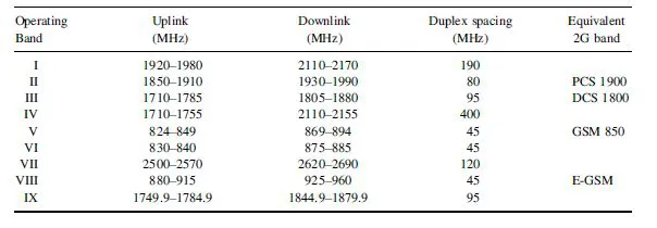
The UMTS air-interface makes use of separate RF carriers for the uplink and downlink. This approach is known as Frequency Division Duplexing (FDD) and is in contrast to technologies which use the same RF carrier for both the uplink and downlink. Using the same RF carrier for both the uplink and downlink requires time sharing, i.e. the RF carrier is assigned to the uplink for a period of time and then the RF carrier is assigned to the downlink for a period of time. This approach is known as Time Division Duplexing (TDD). A set of operating bands have been standardised for use by the UMTS airinterface. These operating bands are presented in Table 1.1.
The availability of each operating band depends upon existing spectrum allocations and the strategy of the national regulator. The majority of countries deploying UMTS make use of operating band I as the core set of frequencies. The remaining operating bands can either be used as extension bands or can be used by countries where operating band I is not available. For example, operating band II is used in North America because operating band I is not available. Operating band II cannot be used as an extension for operating band I because the two sets of frequencies overlap with one another. Operating band VIII is commonly viewed as an extension band which benefits from improved coverage performance as a result of using lower frequencies. Operating band VIII is the same as the extended GSM 900 band and so its use for UMTS may require re-farming of any existing GSM 900 allocations.
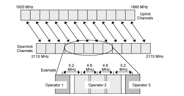
Each operating band is divided into 5 MHz channels. Operating bands I and II have 12 uplink channels and 12 downlink channels. Operating band I has a frequency difference of 190 MHz between the uplink and downlink channels whereas operating band II has a frequency difference of 80 MHz. The difference between the uplink and downlink frequencies is known as the duplex spacing. Large duplex spacings cause more significant differences between the uplink and downlink path loss. The uplink is assigned the lower set of frequencies because the path loss is lower and link budgets are traditionally uplink limited. Small duplex spacings make it more difficult to implement transmit and receive filtering within the UE. Transmit and receive filtering is less of an issue within the Node B because larger and more expensive filters can be used. The uplink and downlink channels belonging to operating band I are illustrated in Figure 1.4.
National regulators award the 5 MHz channels to operators. Those operators then become responsible for deploying and operating UMTS networks. It is common to award between two and four channels to each operator. For example, a country which has four operators could have three channels assigned to each operator. It is possible that not all twelve channels are available and only a subset of the channels are allocated. Once an operator has been assigned a subset of the 5 MHz channels then the operator has some flexibility in terms of configuring the precise centre frequencies of its RF carriers. A UMTS RF carrier occupies less than 5 MHz and so the frequency separation between adjacent RF carriers can also be less than 5 MHz. An example deployment strategy is illustrated in Figure 1.4. In this example, three 5 MHz UMTS channels have been awarded to operator 2 while the adjacent channels have been awarded to operators 1 and 3. Adjacent channel interference mechanisms, e.g. non-ideal transmit filtering and non-ideal receive filtering are less significant when RF carriers are co-sited, or at least coordinated. Operator 2 is likely to co-site adjacent RF carriers which are assigned to the macrocell network (multiple RF carriers assigned to the same Node B) and is likely to coordinate adjacent RF carriers which are assigned to the microcell layer or to any indoor solutions. The Node B belonging to operators 1 and 3 may be neither co-sited nor coordinated with the Node B belonging to operator 2. Operator 2 can help to reduce the potential for any adjacent channel interference by reducing the frequency separation between its own RF carriers. This allows an increased frequency separation from the adjacent operators. The RF carriers within operating band I have been standardised using a 200 kHz channel raster. This means that the centre frequency of each RF carrier can be adjusted with a resolution of 200 kHz.
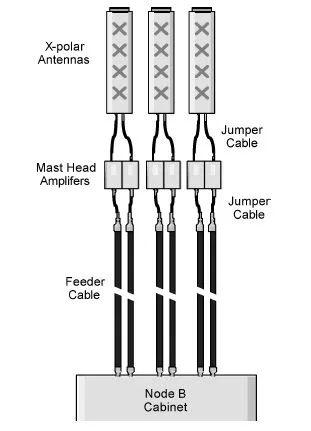
The Node B configuration defines characteristics such as the number of sectors and the number of RF carriers. The most common configuration for initial network deployment is three sectors with one RF carrier. This is known as a 1+1+1 Node B configuration. It requires at least three antennas to be connected to the Node B cabinet, i.e. at least one antenna serving each sector. If uplink receive diversity or downlink transmit diversity is used then either six single element antennas or three dual element antennas are required. If six single element antennas are used then there should be spatial isolation between the two antennas belonging to each sector. This tends to be less practical than using three dual element antennas. It is common to use cross polar antennas which accommodate two antenna elements within each antenna housing. In this case, isolation is achieved in the polarisation domain rather than the spatial domain. Figure 1.5 illustrates an example 1+1+1 Node B configuration using cross polar antennas.
When diversity is used then a separate RF feeder is required for each diversity branch. A 1+1+1 Node B with uplink receive diversity requires six RF feeders to connect the antennas to the Node B cabinet. Likewise, if Mast Head Amplifiers (MHA) are used then six of them would be required. The 1+1+1 Node B configuration has three logical cells, i.e. a logical cell is associated with each sector of the Node B. When the capacity of a single RF carrier becomes exhausted then it is common to upgrade to a second RF carrier. The Node B configuration is then known as a 2+2+2. This configuration has three sectors, but now has two RF carriers and six logical cells. Alternatively, a six sector single RF carrier configuration could be deployed which would be known as a 1+1+1+1+1+1. This configuration also has six logical cells but has six sectors and 1 RF carrier.
When a UMTS operator deploys a single RF carrier then that carrier must be shared between all users of the network and the frequency re-use is 1, i.e. all cells make use of the same RF carrier. GSM networks make use of frequency re-use patterns to assign different RF carriers to neighbouring cells. For example, a frequency re-use of 12 means that the radio network is planned in clusters of 12 cells and each cell within a cluster can use 1/12th of the available RF carriers. This type of approach helps to reduce co-channel interference, but leads to a requirement for hard handovers and a relatively large number of RF carriers. GSM channels have a bandwidth of 200 kHz and so it is possible to place 25 GSM channels within the bandwidth of a single UMTS channel. The use of a wide bandwidth and a frequency re-use of 1 for UMTS provides benefits in terms of receiver sensitivity and spectrum efficiency. The air-interface of a single UMTS cell can support approximately 50 speech users when assuming the maximum Adaptive Multi-Rate (AMR) bit rate of 12.2 kbps. A single GSM RF carrier can support a maximum of 8 speech users when assuming Full Rate (FR) connections. This means that 5 MHz of GSM spectrum can support a maximum of 200 speech users (ignoring the impact of the broadcast channel which in practise would reduce the maximum number of GSM speech users). Assuming a frequency reuse of 10 reduces this figure to 20 speech users per 5 MHz in contrast to the 50 speech users supported by UMTS. The spectrum efficiency of GSM can approach that of UMTS when using small frequency re-use patterns which require more careful planning to avoid co-channel interference. Frequency hopping can also be used to improve the performance and spectrum efficiency of GSM. The number of speech users supported by both UMTS and GSM can be increased by decreasing the bit rates assigned to each connection. The UMTS AMR codec supports bit rates ranging from 4.75 to 12.2 kbps. The GSM Half Rate (HR) feature may be used to reduce the GSM speech bit rate.
GSM RF carriers are shared between multiple connections using Time Division Multiple Access (TDMA). A GSM radio frame is divided into eight time slots and these time slots can be assigned to different connections. An RF carrier belonging to a cell is never simultaneously assigned to more than one connection. A GSM speech connection is assigned different time slots within the radio frame for the uplink and downlink, i.e. the GSM MS does not have to simultaneously transmit and receive. This approach is known as half-duplex and tends to make the MS design easier and less expensive. GSM base stations have to simultaneously transmit and receive because they serve multiple connections and the uplink time slot of one connection can coincide with the downlink time slot of another connection. This is known as full-duplex operation.
UMTS RF carriers are shared between multiple connections using Code Division Multiple Access (CDMA). CDMA allows multiple connections to simultaneously use the same RF carrier. Instead of being assigned time slots, connections are assigned codes. These codes are used to mask the transmitted signal and allow the receiver to distinguish between signals belonging to different connections. The RNC assigns codes t...