Reinforced Concrete Beams, Columns and Frames
eBook - ePub

Reinforced Concrete Beams, Columns and Frames

Mechanics and Design

  1. English
  2. ePUB (mobile friendly)
  3. Available on iOS & Android
eBook - ePub

Reinforced Concrete Beams, Columns and Frames

Mechanics and Design

About this book

This book is focused on the theoretical and practical design of reinforced concrete beams, columns and frame structures. It is based on an analytical approach of designing normal reinforced concrete structural elements that are compatible with most international design rules, including for instance the European design rules – Eurocode 2 – for reinforced concrete structures. The book tries to distinguish between what belongs to the structural design philosophy of such structural elements (related to strength of materials arguments) and what belongs to the design rule aspects associated with specific characteristic data (for the material or loading parameters). Reinforced Concrete Beams, Columns and Frames – Mechanics and Design deals with the fundamental aspects of the mechanics and design of reinforced concrete in general, both related to the Serviceability Limit State (SLS) and the Ultimate Limit State (ULS). A second book, entitled Reinforced Concrete Beams, Columns and Frames – Section and Slender Member Analysis, deals with more advanced ULS aspects, along with instability and second-order analysis aspects. Some recent research results including the use of non-local mechanics are also presented. This book is aimed at Masters-level students, engineers, researchers and teachers in the field of reinforced concrete design. Most of the books in this area are very practical or code-oriented, whereas this book is more theoretically based, using rigorous mathematics and mechanics tools.

Contents

1. Design at Serviceability Limit State (SLS).
2. Verification at Serviceability Limit State (SLS).
3. Concepts for the Design at Ultimate Limit State (ULS).
4. Bending-Curvature at Ultimate Limit State (ULS).
Appendix 1. Cardano's Method.
Appendix 2. Steel Reinforcement Table.

About the Authors

Charles Casandjian was formerly Associate Professor at INSA (French National Institute of Applied Sciences), Rennes, France and the chairman of the course on reinforced concrete design. He has published work on the mechanics of concrete and is also involved in creating a web experience for teaching reinforced concrete design – BA-CORTEX.
Noël Challamel is Professor in Civil Engineering at UBS, University of South Brittany in France and chairman of the EMI-ASCE Stability committee. His contributions mainly concern the dynamics, stability and inelastic behavior of structural components, with special emphasis on Continuum Damage Mechanics (more than 70 publications in International peer-reviewed journals).
Christophe Lanos is Professor in Civil Engineering at the University of Rennes 1 in France. He has mainly published work on the mechanics of concrete, as well as other related subjects. He is also involved in creating a web experience for teaching reinforced concrete design – BA-CORTEX.
Jostein Hellesland has been Professor of Structural Mechanics at the University of Oslo, Norway since January 1988. His contribution to the field of stability has been recognized and magnified by many high-quality papers in famous international journals such as Engineering Structures, Thin-Walled Structures, Journal of Constructional Steel Research and Journal of Structural Engineering.

Frequently asked questions

Yes, you can cancel anytime from the Subscription tab in your account settings on the Perlego website. Your subscription will stay active until the end of your current billing period. Learn how to cancel your subscription.
No, books cannot be downloaded as external files, such as PDFs, for use outside of Perlego. However, you can download books within the Perlego app for offline reading on mobile or tablet. Learn more here.
Perlego offers two plans: Essential and Complete
  • Essential is ideal for learners and professionals who enjoy exploring a wide range of subjects. Access the Essential Library with 800,000+ trusted titles and best-sellers across business, personal growth, and the humanities. Includes unlimited reading time and Standard Read Aloud voice.
  • Complete: Perfect for advanced learners and researchers needing full, unrestricted access. Unlock 1.4M+ books across hundreds of subjects, including academic and specialized titles. The Complete Plan also includes advanced features like Premium Read Aloud and Research Assistant.
Both plans are available with monthly, semester, or annual billing cycles.
We are an online textbook subscription service, where you can get access to an entire online library for less than the price of a single book per month. With over 1 million books across 1000+ topics, we’ve got you covered! Learn more here.
Look out for the read-aloud symbol on your next book to see if you can listen to it. The read-aloud tool reads text aloud for you, highlighting the text as it is being read. You can pause it, speed it up and slow it down. Learn more here.
Yes! You can use the Perlego app on both iOS or Android devices to read anytime, anywhere — even offline. Perfect for commutes or when you’re on the go.
Please note we cannot support devices running on iOS 13 and Android 7 or earlier. Learn more about using the app.
Yes, you can access Reinforced Concrete Beams, Columns and Frames by Charles Casandjian,Noël Challamel,Christophe Lanos,Jostein Hellesland in PDF and/or ePUB format, as well as other popular books in Physical Sciences & Mechanics. We have over one million books available in our catalogue for you to explore.

Information

Publisher
Wiley-ISTE
Year
2013
Print ISBN
9781848214828
eBook ISBN
9781118639467
Edition
1
Subtopic
Mechanics

Chapter 1

Design at Serviceability Limit State (SLS)

1.1. Nomenclature

1.1.1. Convention with the normal vector orientation

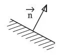
The normal vector is chosen to be oriented toward the external part of the considered body. The usual conventions of mechanics of continuous media are chosen, leading to a positive stress for tension and a negative stress for compression.
Figure 1.1. Definition of the normal unit
ch01_image001.webp

1.1.2. Vectorial notation

As opposite to the notation used for figures, where vectors are represented with an arrow, in the text, vectors are denoted by bold characters and its components have normal non-bold characters. As an example, we will have “M = Mxi+ Myj + Mzk”.

1.1.3. Part of the conserved reference section

The conserved reference part of the beam used for the calculation of generalized stress in use of the static theorems is the “right” part.
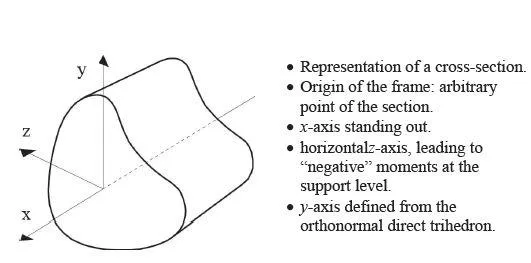
1.1.4. Frame

Figure 1.2. Orientation of the frame for a general section
ch01_image002.webp

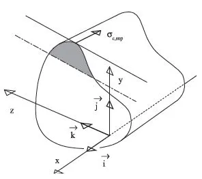
1.1.5. Compression stress σc,sup in the most compressed fiber

It is admitted that the neutral axis is located inside the cross-section, thus delimiting a tension zone and a compressed zone. This last assumption of a neutral axis inside the cross-section is no more valid when considering additional meaningful normal forces. Typically, under a positive moment (in span), the tension zone is located under the neutral axis, and the compression zone above the neutral axis, as shown in Figure 1.3. Obviously, in the presence of a negative bending moment, the tension zone and the compression zone are permuted with respect to the notation of Figure 1.3. The neutral axis as shown in Figure 1.3 allows the introduction of the concept of extremal compressed fiber, defined from the most distant parallel to the neutral axis belonging to the cross-section. The most compressed fiber in concrete is by definition the fiber associated with the minimal compressive stress in algebraic value, denoted by σc,sup .
Figure 1.3. Concept of extremal compressed fiber
ch01_image003.webp

1.2. Bending behavior of reinforced concrete beams – qualitative analysis

1.2.1. Framework of the study

1.2.1.1. Constitutive law of concrete

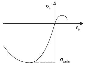
The constitutive law of concrete is a strong unsymmetrical law in tension and in compression, both from the strength and the postfailure response, which is characterized by its ductility (see Figure 1.4). As a natural choice, the subscript c refers to concrete whereas the subscript s refers to the steel material. We adopt by σc,min the extreme stress at the compression peak.
Figure 1.4. Unsymmetrical response of concrete in uniaxial tension and compression
ch01_image004.webp

1.2.1.2. Beam theory in simple bending

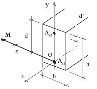
In this section, reinforced concrete beams in simple bending are studied (without axial forces), composed of a rectangular cross-section with a total height denoted by h and a width b. This section is reinforced by some steel reinforcement working in tension with a cross-section denoted by As1 and by steel reinforcement working in compression with a cross-section denoted by As2. The center of gravity of the tensile reinforcement is at a distance d of the upper fiber, and one of the compression reinforcements is at a distance d' of the upper fiber of the cross-section.
Figure 1.5. Geometrical parameters of the reinforced cross-section; tensile and compression steel reinforcement
ch01_image005.webp
In this case, again, it is implicitly accepted that the bending solicitation corresponds to a positive moment (the lower fibers are in tension with this convention, typically in span). Designing under negative moment (typically at support, for instance) is formally feasible by permuting the behavior of the cross-section. Furthermore, we can introduce the strain εs1 as the strain of the tensile reinforcement with the largest tensile stress σs1 and with the reinforcement area As1.

1.2.2. Classification of cross-sectional behavior

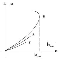
Three kinds of reinforced concrete beam responses can be distinguished, depending on the steel reinforcement density (Figure 1.6). These responses are explicitly detailed in the space of the bending moment with respect to the stress in the most compressed fiber in concrete.
Figure 1.6. Bending behavior of reinforced concrete beams with respect to the steel reinforcement density
ch01_image006.webp
F: brittle response, which appears when the beam design does not respect the condition of non-brittleness.
A: beam with low steel reinforcement density, characterized by a global ductile response. Failure is induced by a large drawing of the tensile steel reinforcement. As discussed below, the letter A refers to Pivot A.
B: beam with high steel reinforcement density, characterized by the breaking up of the compressed part of the upper part concrete. The letter B refers to the behavior classified as Pivot B.
In the following, brittle reinforced concrete beams of type F will not be investigated.

1.2.3. Parameterization of the response curves by the stress σs1 of the most stressed tensile reinforcement

In Figure 1.7, the response curves are parameterized by the stress σs1 of the most stressed tensile reinforcement. When reading Figure 1.7 in the...

Table of contents

  1. Cover
  2. Contents
  3. Title page
  4. Copyright page
  5. Preface
  6. Chapter 1: Design at Serviceability Limit State (SLS)
  7. Chapter 2: Verification at Serviceability Limit State (SLS)
  8. Chapter 3: Concepts for the Design at Ultimate Limit State (ULS)
  9. Chapter 4: Bending-Curvature at Ultimate Limit State (ULS)
  10. Appendix 1: Cardano’s Method
  11. Appendix 2: Steel Reinforcement Table
  12. Bibliography
  13. Index