![]()
1
INTRODUCTION
1.1 What Geophysics Measures
Applied or exploration geophysics can be defined as mapping the subsurface through the remote measurement of its physical properties. The discipline dates back to ancient times but only since the advent of modern-day instrumentation has its use become widespread. The development of geophysical techniques and equipment during the early to middle parts of the twentieth century was driven by oil and mineral exploration, for targets that could be several kilometres deep. Many of the instruments used today in archaeological, environmental and engineering surveys owe their development to this kind of geophysics, but have been adapted to investigations of the near-surface, in the range of 0.5–100m.
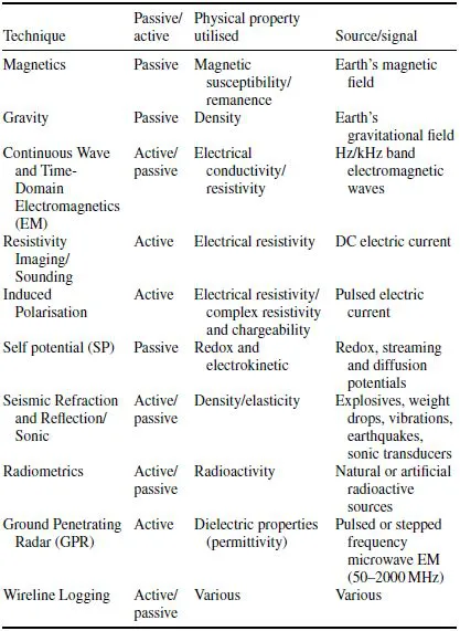
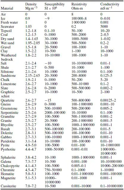
The success of any geophysical method relies on there being a measurable contrast between the physical properties of the target and the surrounding medium. The properties utilised are, typically, density, elasticity, magnetic susceptibility, electrical conductivity and radioactivity (Table 1.1). Whether a physical contrast is in practice measurable is inextricably linked to the physics of the problem, the design of the geophysical survey and the selection of suitable equipment. Not all equipment is fit for purpose. Often a combination of methods provides the best means of solving a complex problem, and sometimes a target that does not provide a measurable physical contrast can be detected indirectly by its association with conditions or materials that do. One of the aims of this handbook is to give the field observer an appreciation of the notional detectability of targets and the influence of burial setting, survey design, equipment selection and operating procedures on actual detectability.
1.2 Fields
Although there are many different types of geophysical measurement, small-scale surveys all tend to be rather similar and involve similar, and sometimes ambiguous, jargon. For example, the word base has three different common meanings, and stacked and field have two each.
Measurements in geophysical surveys are made in the field but, unfortunately, many are also of fields. Field theory is fundamental to gravity, magnetic and electromagnetic (EM) work, and even particle fluxes and seismic wavefronts can be described in terms of radiation fields. Sometimes ambiguity is unimportant, and sometimes both meanings are appropriate (and intended), but there are occasions when it is necessary to make clear distinctions. In particular, the term field reading is nearly always used to identify readings made in the field, i.e. not at a base station.
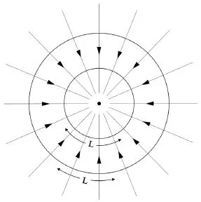
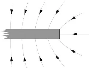
Physical fields can be illustrated by lines of force that show the field direction at any point (Figure 1.1). Intensity can also be indicated, by using more closely spaced lines for strong fields, but it is difficult to do this quantitatively where three-dimensional situations are being illustrated on two-dimensional media.
In Table 1.1 there is a broad division into passive and active methods. Passive methods use naturally occurring fields (such as the Earth’s magnetic field), over which the observer has no control, and detect variations caused by geology or man-made objects. Interpretation is usually non-unique, relying a great deal on the experience of the interpreter. Active methods involve generating signals in order to induce a measurable response associated with a target. The observer can control the level of energy input to the ground and also measure variations in energy transmissibility over distance and time. Interpretation of this type of data can be more quantitative. Depth discrimination is often better than with passive methods, but ease of interpretation is not guaranteed.
1.2.1 Vector addition
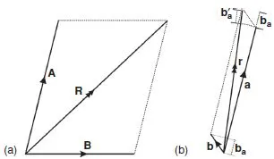
When combining fields from different sources, vector addition (Figure 1.2) must be used. In passive methods, knowledge of the principles of vector addition is needed to understand the ways in which measurements of local anomalies are affected by regional backgrounds. In active methods, a local anomaly (secondary field) is often superimposed on a primary field produced by a transmitter. In either case, if the local field is much the weaker of the two (in practice, less than one-tenth the strength of the primary or background field), then the measurement will, to a first approximation, be made in the direction of the stronger field and only the component of the anomaly in that direction will be measured (Figure 1.2b). The slight difference in direction between the resultant and the background or primary field is usually ignored in such cases.
If the two fields are similar in strength, there will be no simple relationship between the magnitude of the anomalous field and the magnitude of the observed anomaly. However, variations in any given component of the secondary field can be measured by taking all measurements in a single direction and assuming that the component of the background or primary field in that direction is constant over the survey area. Measurements of vertical rather than total field are sometimes preferred in magnetic and electromagnetic surveys for this reason.
The fields due to multiple sources are not necessarily equal to the vector sums of the fields that would have existed had those sources been present in isolation. A strong magnetic field from one body can affect the magnetisation in another, or even in itself (demagnetisation effect), and the interactions between fields, conductors and currents in electrical and electromagnetic surveys can be very complicated.
1.2.2 The inverse-square law
An inverse-square law attenuation of signal strength occurs in most branches of applied geophysics. It is at its simplest in gravity work, where the field due to a point mass is inversely proportional to the square of the distance from the mass, and the constant of proportionality (the gravitational constant G) is invariant. Magnetic fields also obey an inverse-square law, and the fact that, in principle, their strength varies with the permeability of the medium is irrelevant in most geophysical work, where measurements are made in either air or water. More important is the fact, which significantly modifies the simple inverse-square law decrease in field strength, that magnetic sources are essentially bipolar (Section 1.2.5).
Electric current flowing from an isolated point-electrode embedded in a continuous homogeneous ground provides a physical illustration of the significance of the inverse-square law. All of the current radiating from the electrode must cross any closed surface that surrounds it. If this surface is a sphere concentric with the electrode, the same fraction of the total current will cross each unit area on the surface of the sphere. The current per unit area will therefore be inversely proportional to the total surface area, which is in turn proportional to the square of the radius. Current flow in the real Earth is, of course, drastically modified by conductivity variations.
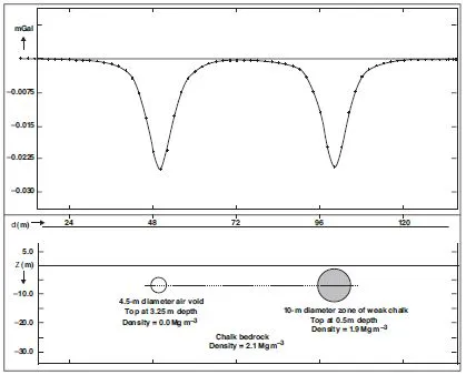
One problem inherent in the inverse-square law control of so many of the fields important in geophysics is ambiguity, i.e. the fact that a set of measurements made over a single surface can, in principle, be produced by an infinite number of possible source distributions. Most of these will be geologically impossible, but enough usually remain to render non-geophysical information essential to most interpretations. Figure 1.3 shows two spherical bodies, each with its centre at 5.5 m depth. One, an air void, has a radius of 2.25 m and zero density, whereas the other, a zone of weathered chalk, has a radius of 5 m and a density of 1.9 Mg m−3. The surrounding rock is modelled with the density of 2.1 Mg m−3 typical of more competent chalk. The gravitational attraction of each sphere can be calculated assuming the mass deficit is concentrated at its centre. The two anomalies are almost identical, and a follow-on intrusive investigation of each, or a survey using a corroborative geophysical method such as electrical resistivity tomography (Section 6.5) would be required to resolve the ambiguity. Even non-identical anomalies may, of course, differ by amounts so small that they cannot be distinguished in field data.
Ambiguity worries interpreters more than it does the observers in the field, but its existence does emphasise the importance of those observers including in their field notes anything that might possibly contribute to a better understanding of the data that they collect.
1.2.3 Two-dimensional sources
Rates of decrease in field strengths depend on source shapes as well as on the inverse-square law. Infinitely long sources of constant cross-section are termed two-dimensional (2D) and are often used in computer modelling to approximate bodies of large strike extent. If the source ‘point’ in Figure 1.1 represents an infinite line-source seen end-on rather than an actual point, the area of the enclosing (cylindrical) surface is proportional to its radius. The argument applied in the previous section to a point source then leads to the conclusion that the field strength for a line-source will be inversely proportional to distance and not to its square. It follows that, in 2D situations, lines of force drawn on pieces of paper can indicate field intensity (by their separation) as well as direction.
1.2.4 One-dimensional sources
The lines of force or radiation intensity from a source consisting of a homogeneous layer of constant thickness diverge only near its edges (Figure 1.4). The Bouguer plate of gravity reductions (Section 2.5.1) and the radioactive source with 2π geometry (Section 4.3.4) are examples of infinitely extended layer sources, for which field strengths are independent of distance. This condition is approximately achieved if a detector is only a short distance above an extended source and a long way from its edges.
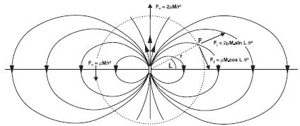
1.2.5 Dipoles
A dipole consists of equal-strength positive and negative point sources a very small distance apart. Its moment is equal to the pole strength multiplied by the separation distance. Field strength decreases as the inverse cube of distance, and both strength and direction change with ‘latitude’ (Figure 1.5). The intensity of the field at a point on a dipole ‘equator’ is only half the intensity at a point the same distance away on the dipole axis, and in the opposite direction.
Magnetisation is fundamentally dipolar, and electric currents circulating in small loops are dipolar sources of magnetic field. Many radar antennas are dipolar, and in some electrical surveys the electrodes are set out in approximately dipole pairs.
1.2.6 Exponential decay
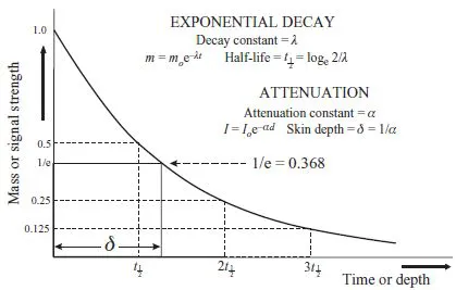
Radioactive particle fluxes and seismic and electromagnetic waves are subject to absorption as well as geometrical attenuation, and the energy crossing closed surfaces is less than the energy emitted by the sources they enclose. In homogeneous media, the percentage loss experienced by a plane wave is determined by the path length and the attenuation constant. The absolute loss is proportional also to the signal strength. A similar exponential law (Figure 1.6), governed by a decay constant, determines the rate of loss of mass by a radioactive substance.
Attenuation rates are alternatively characterised by skin-depths, which are the reciprocals of attenuation constants. For each skin depth travelled, the signal strength decreases to 1/e of its original value, where e (= 2.718) is the base of natural logarithms. Radioactive decay rates are normally described in terms of the half-lives, equal to loge2 (= 0.693) divided by the decay constant. During each half-life period, one half of the material present at its start is lost.
1.3 Geophysical Survey Design
1.3.1 Will geophysics work?
Geophysical techniques cannot be applied indiscriminately. Knowledge of the material properties likely to be associated with a target (and its burial setting) is essential to choosing the correct method(s) and interpreting the results obtained.
Armed with such knowledge, the geophysicist can assess feasibility and, where possible, select a geophysical method to meet the survey objectives. Table 1.2 lists some of the more important physical properties, for some of the commoner rocks and minerals. Inevitably, the values given are no more than broad generalisations, but the table does at least indicate some of the circumstances in which large contrasts in physical properties might be expected, or at least be hoped for.
The design and implementation of a geophysical survey requires careful consideration of the following main factors:
(a) Target discrimination
The nature and degree of the contrast in physical properties between a target and its surroundings is of primary importance in the feasibility assessment and choice of techniques. However, information may be limited or non-existent, and in these cases the geophysicist should recommend a trial survey or the application of multiple techniques. Trials are recommended wherever the assumptions made in designing the survey are suspect. Usually a day is all that is required to determine whether the chosen methods can detect the presence of a target in actual field conditions. This is an often neglected stage in the execution of a geophysical survey but is one that could save much geophysicist’s pride and client’s money were it more routinely used.
Once it has been decided, on the basis of observation, modelling and/or experience, what the geophysical response of a buried target is likely to be, the sensitivity of the equipment and the distribution of the survey stations needed to meet the survey objectives can be specified.
(b) Detection distance
In addi...