Just like building physics, performance based building design was hardly an issue before the energy crises of the 1970ies. With the need to upgrade energy efficiency, the interest in overall building performance grew. The term "performance" encompasses all building-related physical properties and qualities that are predictable during the design stage and controllable during and after construction. The term "predictable" demands calculation tools and physical models that allow evaluating a design, whereas "controllable" presumes the existence of measuring methods available on site. The basis for a system of performance arrays are the functional demands, the needs for accessibility, safety, well-being, durability, energy efficiency and sustainability and the requirements imposed by the usage of a building.
In continuation of Vol. 1 this second volume discusses light-weight construction with wooden and metal elements, roofing systems, facades, and ends with finishes and the overall risk analysis. Most chapters build on a same scheme: overview, overall performance evaluation, design and construction. The work is absolutely recommended to undergraduates and graduates in architectural and building engineering, though also building engineers, who want to refresh their knowledge, may benefit. The level of discussion assumes the reader has a sound knowledge of building physics, along with a background in structural engineering, building materials and building construction. Where and when needed, input and literature from over the world was used, reason why each chapter ends listing references and literature.
Trusted by 375,005 students
Access to over 1.5 million titles for a fair monthly price.
In the Low Countries on the North Sea, timber was the common construction material for rural and municipal dwellings until the 13th – 14th century. Brick construction was an aristocrat’s privilege. Many devastating town fires, the sociological fact that bricks stood for wealth and growing wood shortages slowly turned brick building into the new standard.
Timber construction still is the reference in many countries worldwide, like the US, Canada, Norway, Sweden, Finland, Russia, Japan and other countries rich in forests and often with a cold climate. There, the framed type has an important advantage compared to massive construction: it is easy to insulate, which is why even in northwest Europe timber-frame construction has regained popularity, now for passive houses. However, the disadvantages also deserve mentioning: hardly any thermal inertia, air tightness critical and less moisture tolerant than brick construction.
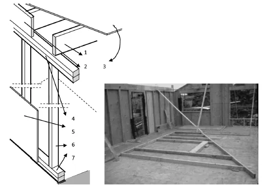
In timber framing, load- and non-bearing outer and partitions walls consist of a framework of timber studs and crossbeams, called plates. The outer wall frames are externally finished with structural sheathing. Where the studs bear all vertical loads and the outer wall ones have also to withstand the wind component, normal to the façade, the sheathing provides overall stiffness against horizontal loading. It also prevents buckling of the studs parallel to their lowest inertia radius. From the three common framing approaches – platform, balloon, post and beam – the platform type, composed of storey-high stud walls and timber floors is the most popular (Figure 1.1).
Construction looks as follows: once the foundations and foundation walls are ready, the ground floor is laid, in humid climates preferably a concrete deck, though in dry climates also timber joists with plywood or OSB (oriented strand board) deck apply, the crosscut end sides being closed with header plates. In such case, ripped half-width standard timber beams form the floor joists with struts at half-span excluding lateral buckling. Then one fixes the bottom plates, after which the studs are nailed and coupled with top plates. To stabilize the frame corners, doubling these is an option. After, a plywood, OSB or stiff insulation board (XPS) sheathing is nailed to the outer wall frames. The joists of the second floor, which are fixed at the top plates then follow. Header plates again close the crosscut end sides and plywood or OSB forms the running surface. The same cycle restarts for the second storey: bottom plate, studs, top plates, sheathing, floor joists, running surface, etc.
A timber framework or rafters, axis to axis at the same distance as the studs, shape the loadbearing roof structure with an external sheathing once more providing stiffness. Timber framing ends with wrapping up the outer walls with waterproof, wind tight building paper, stapled from bottom to top on the sheathing with the higher strips overlapping the lower ones. Platform framing lends itself to modular construction and prefabrication.
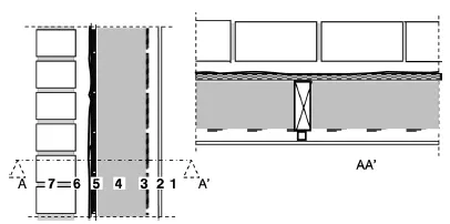
From inside to outside the outer wall assembly looks like (Figure 1.2): inside lining (gypsum board); (service cavity); air (always) and vapour (when necessary) retarder; bays between studs filled with insulation (mineral wool or cellulose); plywood, OSB or stiff insulation board sheathing; building paper; outside finish (timber siding, brick veneer, EIFS, etc).
Aside from timber framing, also metal framed construction exists, with metal studs and plates replacing the timber ones.
Figure 1.2. Timber-framed outer wall, reference assembly (1: inside lining, 2: service cavity, 3: air and vapour retarder, 4: thermal insulation; 5: sheathing, 6: building paper, 7: outside finish).
1.2 Performance evaluation
1.2.1 Structural integrity
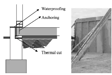
Timber-framed buildings are so lightweight that anchoring in the foundation walls is necessary to prevent displacement under extreme wind load (Figure 1.3).
Figure 1.3. Timber-framed construction, anchoring in the foundation walls.
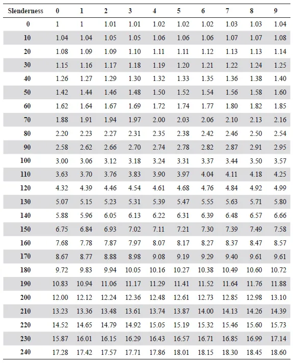
Wind loading and buckling of the outer and partition wall studs demands proper attention. The sheathing or inside finishes block it in the lowest moment of inertia direction. The direction normal to the walls needs a control. Table 1.1 gives the buckling factors vertical loads have to be multiplied by, as a function of the stud’s slenderness (i):
(1.1)
with L the effective stud span (in timber framed construction equal to the distance between bottom and top plates), I the moment of inertia around the neutral axis of the combination stud/sheathing (if shear-stiff coupled) and A total active cross section.
If this product gives stresses in the timber beyond acceptable, or, if for a given span the stud’s radius of inertia is too low, then two options are left: diminishing the centre-to-centre distance between studs or using deeper ones. The first is disadvantageous in terms of whole wall thermal transmittance whereas the second allows larger insulation thicknesses, thus, a lower whole wall thermal transmittance.
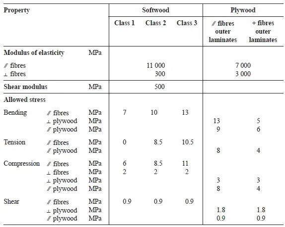
Table 1.2 summarizes the mechanical properties of softwood and plywood. For the stiffness against horizontal loads, the same rules as for massive construction hold: the floors as rigid horizontal decks, at least 3 sheathed or wind-braced walls whose centre planes do not cross in one point, the stiff walls preferentially distributed in a way the resulting wind load vector crosses their stiffness centre.
Table 1.1. Buckling factors (slenderness vertically in steps of 10, horizontally in steps of 1).
Table 1.2. Mechanical properties of softwood and plywood.
1.2.2 Building physics: heat, air, moisture
1.2.2.1 Air tightness
Air tightness of timber-framed envelopes is not taken for granted. The outside finish, the building paper, the sheathing, as well as the insulation, all are air-permeable. Contributing factors are, for the building paper, the overlaps between the strips, for the sheathing the joints between boards and for the thermal insulation the material itself and the gaps between insulation, studs and plates. It is the inside finish to guarantee air-tightness. Non-perforated gypsum board linings without cracks between boards have an air permeance of (Ka) ≈ 3.1 · 10–5 ΔPa–0.19. For an air pressure difference of 10 Pa, that value limits air leakage to 0.43 m3/(m2 · h). However, when sockets and others perforate the lining and cracks form between boards, this value may increase by a factor of 10, which is why inclusion of an additional air barrier deserves recommendation. In moderate and cold climates, one used a PE-foil, stapled against the timber frame, preferentially with a service cavity left between foil and inside lining. Recently, OSB with taped joints emerged as an alternative (Figure 1.4). But also with additional air barrier, perfect air-tightness is hard to realize. Even excellent workmanship did not result in tested air leakages below 3 dm3/(m2 · h) at 1 Pa air pressure difference. In hot and humid climates, it is up to the outside finish to guarantee air-tightness.
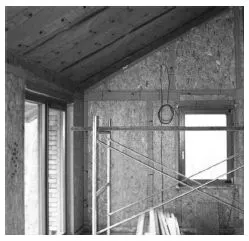
Figure 1.4. Taped OSB as air barrier.
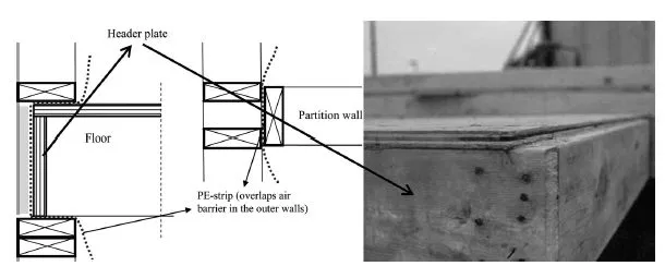
Figure 1.5. Timber-framed construction: caring for a continuous air barrier in the envelope.
Also three-dimensionally, a timber-framed construction offers a network of leaks. Via the junctions with the envelope, outside air may permeate partition walls, while conversely inside air can flow to the outside through the sockets in the partitions. At each floor level, air may flow façade to façade between the joists, a phenomenon causing unexpectedly high heat losses, quick ceiling soiling, and mould where the outside air enters. All this demands an envelope with continuous air barrier. Therefore, the following recommendations prevail: (1) include PE-strips at each floor between header plate and header insulation, (2) fix PE-strips in all junctions between outer and partition walls, (3) tape the overlaps to the air barrier (Figure 1.5).
Fully filling the space between sheathing and air barrier prevents air looping along the thermal insulation. A hotbox test on a two meters high timber framed wall insulated with 8 cm thick XPS-boards demonstrated that partial fills are critical. These are too stiff to link up perfectly with studs, plates, sheathing, and inside lining, creating leaks across and air layers at both sides of the insulation that way. At a temperature difference of 18.7 °C there was no uniform heat loss of 4.5 W/m2 but large differences between the flow rates up and down the inside and outside surface were noted, see Table 1.3.
Table 1.3. Hot box test: heat flow rate across a timber-framed wall (Uo = 0.24 W/(m2 · K)).
Heightm
Heat flow rateW/m2
outside surface
inside surface
1.7
30.9
3.7
0.3
5.7
11.5
The reason is air looping, with cold air rising at the warm side of the insulation, warm air falling at the cold side, changeover from warm to cold on top of the insulation and changeover from cold to warm down the insulation. The data also suggest that thermal stack between hot and cold box activates outflow up, and inflow down the wall.
The building paper wrap should guarantee wind-tightness.
1.2.2.2 Thermal transmittance
The discussion relates to outer walls only. For roofs and floors, reference is made to the chapter on floors in Performance Based Building Design 1 and the chapters that follow on roofs. As always, the clear and whole wall thermal transmittances (U) differ, the last accounting for studs, top and bottom plates. In the case of an airtight outer wall, the series/parallel circuit of Figure 1.6 allows a fair guess of the whole wall thermal transmittance, as do also the following linear thermal transmittances (ψ):
Stud
Bottom plate
Top plates
ψ = 0.017 W/(m · K)
ψ = 0.010 W/(m · K)
ψ = 0.023 W/(m · K)
With mineral wool or cellulose as thermal insulation and a brick veneer as outside finish, the thicknesses of Table 1.4 give whole wall thermal transmittances of 0.4, 0...
Table of contents
Cover
Titlepage
Copyright page
Dedication
Preface
0: Introduction
1: Timber-framed construction
2: Sheet-metal outer wall systems
3: New developments
4: Roofs: requirements
5: Low-sloped roofs
6: Pitched roofs
7: Sheet-metal roofs
8: Windows, outer doors and glass façades
9: Balconies, shafts, chimneys and stairs
10: Partitions; wall, floor and ceiling finishes; inside carpentry
11: Risk analysis
Frequently asked questions
Yes, you can cancel anytime from the Subscription tab in your account settings on the Perlego website. Your subscription will stay active until the end of your current billing period. Learn how to cancel your subscription
No, books cannot be downloaded as external files, such as PDFs, for use outside of Perlego. However, you can download books within the Perlego app for offline reading on mobile or tablet. Learn how to download books offline
Perlego offers two plans: Essential and Complete
Essential is ideal for learners and professionals who enjoy exploring a wide range of subjects. Access the Essential Library with 800,000+ trusted titles and best-sellers across business, personal growth, and the humanities. Includes unlimited reading time and Standard Read Aloud voice.
Complete: Perfect for advanced learners and researchers needing full, unrestricted access. Unlock 1.5M+ books across hundreds of subjects, including academic and specialized titles. The Complete Plan also includes advanced features like Premium Read Aloud and Research Assistant.
Both plans are available with monthly, semester, or annual billing cycles.
We are an online textbook subscription service, where you can get access to an entire online library for less than the price of a single book per month. With over 1.5 million books across 990+ topics, we’ve got you covered! Learn about our mission
Look out for the read-aloud symbol on your next book to see if you can listen to it. The read-aloud tool reads text aloud for you, highlighting the text as it is being read. You can pause it, speed it up and slow it down. Learn more about Read Aloud
Yes! You can use the Perlego app on both iOS and Android devices to read anytime, anywhere — even offline. Perfect for commutes or when you’re on the go. Please note we cannot support devices running on iOS 13 and Android 7 or earlier. Learn more about using the app
Yes, you can access Performance Based Building Design 2 by Hugo S. L. Hens in PDF and/or ePUB format, as well as other popular books in Technology & Engineering & Construction & Architectural Engineering. We have over 1.5 million books available in our catalogue for you to explore.