Aircraft Systems, 3rd Edition is thoroughly revised and expanded from the last edition in 2001, reflecting the significant technological and procedural changes that have occurred in the interim – new aircraft types, increased electronic implementation, developing markets, increased environmental pressures and the emergence of UAVs. Every chapter is updated, and the latest technologies depicted. It offers an essential reference tool for aerospace industry researchers and practitioners such as aircraft designers, fuel specialists, engine specialists, and ground crew maintenance providers, as well as a textbook for senior undergraduate and postgraduate students in systems engineering, aerospace and engineering avionics.
eBook - ePub
Aircraft Systems
Mechanical, Electrical, and Avionics Subsystems Integration
- English
- ePUB (mobile friendly)
- Available on iOS & Android
eBook - ePub
Aircraft Systems
Mechanical, Electrical, and Avionics Subsystems Integration
About this book
This third edition of Aircraft Systems represents a timely update of the Aerospace Series' successful and widely acclaimed flagship title. Moir and Seabridge present an in-depth study of the general systems of an aircraft – electronics, hydraulics, pneumatics, emergency systems and flight control to name but a few - that transform an aircraft shell into a living, functioning and communicating flying machine. Advances in systems technology continue to alloy systems and avionics, with aircraft support and flight systems increasingly controlled and monitored by electronics; the authors handle the complexities of these overlaps and interactions in a straightforward and accessible manner that also enhances synergy with the book's two sister volumes, Civil Avionics Systems and Military Avionics Systems.
Trusted by 375,005 students
Access to over 1 million titles for a fair monthly price.
Study more efficiently using our study tools.
Information
1
Flight Control Systems
1.1 introduction
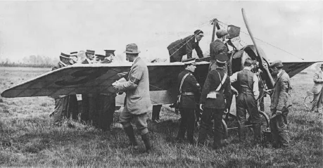
Flight controls have advanced considerably throughout the years. In the earliest biplanes flown by the pioneers flight control was achieved by warping wings and control surfaces by means of wires attached to the flying controls in the cockpit. Figure 1.1 clearly shows the multiplicity of rigging and control wires on an early monoplane. Such a means of exercising control was clearly rudimentary and usually barely adequate for the task in hand. The use of articulated flight control surfaces followed soon after but the use of wires and pulleys to connect the flight control surfaces to the pilot’s controls persisted for many years until advances in aircraft performance rendered the technique inadequate for all but the simplest aircraft.
Figure 1.1 Morane Saulnier Monoplane refuelling before the 1913 Aerial Derby (Courtesy of the Royal Aero Club)
When top speeds advanced into the transonic region the need for more complex and more sophisticated methods became obvious. They were needed first for high-speed fighter aircraft and then with larger aircraft when jet propulsion became more widespread. The higher speeds resulted in higher loads on the flight control surfaces which made the aircraft very difficult to fly physically. The Spitfire experienced high control forces and a control reversal which was not initially understood. To overcome the higher loadings, powered surfaces began to be used with hydraulically powered actuators boosting the efforts of the pilot to reduce the physical effort required. This brought another problem: that of ‘feel’. By divorcing the pilot from the true effort required to fly the aircraft it became possible to undertake manoeuvres which could over- stress the aircraft. Thereafter it was necessary to provide artificial feel so that the pilot was given feedback representative of the demands he was imposing on the aircraft. The need to provide artificial means of trimming the aircraft was required as Mach trim devices were developed.
A further complication of increasing top speeds was aerodynamically related effects. The tendency of many high performance aircraft to experience roll/yaw coupled oscillations – commonly called Dutch roll – led to the introduction of yaw dampers and other auto-stabilisation systems. For a transport aircraft these were required for passenger comfort whereas on military aircraft it became necessary for target tracking and weapon aiming reasons.
The implementation of yaw dampers and auto-stabilisation systems introduced electronics into flight control. Autopilots had used both electrical and air driven means to provide an automatic capability of flying the aircraft, thereby reducing crew workload. The electronics used to perform the control functions comprised analogue sensor and actuator devices which became capable of executing complex control laws and undertaking high integrity control tasks with multiple lanes to guard against equipment failures. The crowning glory of this technology was the Category III autoland system manufactured by Smiths Industries and fitted to the Trident and Belfast aircraft.
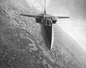
The technology advanced to the point where it was possible to remove the mechanical linkage between the pilot and flight control actuators and rely totally on electrical and electronic means to control the aircraft. Early systems were hybrid, using analogue computing with discrete control logic. The Control and Stability Augmentation System (CSAS) fitted to Tornado was an example of this type of system though the Tornado retained some mechanical reversion capability in the event of total system failure. However the rapid development and maturity of digital electronics soon led to digital ‘fly-by-wire’ systems. These developments placed a considerable demand on the primary flight control actuators which have to be able to accommodate multiple channel inputs and also possess the necessary failure logic to detect and isolate failures (see Figure 1.2).
Most modern fighter aircraft of any sophistication now possess a fly-by-wire system due to the weight savings and considerable improvements in handling characteristics which may be achieved. Indeed many such aircraft are totally unstable and would not be able to fly otherwise. In recent years this technology has been applied to civil transports: initially with the relaxed stability system fitted to the Airbus A320 family and A330/A340. The Boeing 777 airliner also has a digital fly-by-wire system, the first Boeing aircraft to do so.
Figure 1.2 Tornado ADV (F 3) Prototype (Courtesy of BAE Systems)
1.2 Principles of Flight Control
All aircraft are governed by the same basic principles of flight control, whether the vehicle is the most sophisticated high-performance fighter or the simplest model aircraft.
The motion of an aircraft is defined in relation to translational motion and rotational motion around a fixed set of defined axes. Translational motion is that by which a vehicle travels from one point to another in space. For an orthodox aircraft the direction in which translational motion occurs is in the direction in which the aircraft is flying, which is also the direction in which it is pointing. The rotational motion relates to the motion of the aircraft around three defined axes: pitch, roll and yaw. See Figure 1.3.
This figure shows the direction of the aircraft velocity in relation to the pitch, roll and yaw axes. For most of the flight an aircraft will be flying straight and level and the velocity vector will be parallel with the surface of the earth and proceeding upon a heading that the pilot has chosen. If the pilot wishes to climb, the flight control system is required to rotate the aircraft around the pitch axis (Ox) in a nose-up sense to achieve a climb angle. Upon reaching the new desired altitude the aircraft will be rotated in a nose-down sense until the aircraft is once again straight and level.
Figure 1.3 Definition of flight control axes
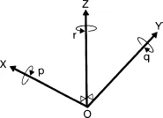
In most fixed wing aircraft, if the pilot wishes to alter the aircraft heading then he will need to execute a turn to align the aircraft with the new heading. During a turn the aircraft wings are rotated around the roll axis (Oy) until a certain bank is attained. In a properly balanced turn the angle of roll when maintained will result in an accompanying change of heading while the roll angle (often called the bank angle) is maintained. This change in heading is actually a rotation around the yaw axis (Oz). The difference between the climb (or descent) and the turn is that the climb only involves rotation around one axis whereas the turn involves simultaneous coordination of two axes. In a properly coordinated turn, a component of aircraft lift acts in the direction of the turn, thereby reducing the vertical component of lift. If nothing were done to correct this situation, the aircraft would begin to descend; therefore in a prolonged turning manoeuvre the pilot has to raise the nose to compensate for this loss of lift. At certain times during flight the pilot may in fact be rotating the aircraft around all three axes, for example during a climbing or descending turning manoeuvre.
The aircraft flight control system enables the pilot to exercise control over the aircraft during all portions of flight. The system provides control surfaces that allow the aircraft to manoeuvre in pitch, roll and yaw. The system has also to be designed so that it provides stable control for all parts of the aircraft flight envelope; this requires a thorough understanding of the aerodynamics and dynamic motion of the aircraft. As will be seen, additional control surfaces are required for the specific purposes of controlling the high lift devices required during approach and landing phases of flight. The flight control system has to give the pilot considerable physical assistance to overcome the enormous aerodynamic forces on the flight control surfaces. This in turn leads to the need to provide the aircraft controls with ‘artificial feel’ so that he does not inadvertently overstress the aircraft. These ‘feel’ systems need to provide the pilot with progressive and well-harmonised controls that make the aircraft safe and pleasant to handle. A typical term that is commonly used today to describe this requirement is ‘carefree handling’. Many aircraft embody automatic flight control systems to ease the burden of flying the aircraft and to reduce pilot workload.
1.3 Flight Control Surfaces
The requirements for flight control surfaces vary greatly between one aircraft and another, depending upon the role, range and agility needs of the vehicle. These varying requirements may best be summarised by giving examples of two differing types of aircraft: an agile fighter aircraft and a typical modern airliner.
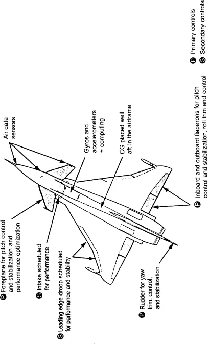
The (Experimental Aircraft Programme) EAP aircraft is shown in Figure 1.4 and represented the state of the art fighter aircraft as defined by European Manufacturers at the beginning of the 1990s. The EAP was the forerunner to the European Fighter Aircraft (EFA) or Eurofighter Typhoon developed by the four nation consortium comprising Alenia (Italy), British Aerospace (UK), CASA (Spain) and DASA (Germany).
1.4 Primary Flight Control
Primary flight control in pitch, roll and yaw is provided by the control surfaces described below.
Pitch control is provided by the moving canard surfaces, or foreplanes, as they are sometimes called, located either side of the cockpit. These surfaces provide the very powerful pitch control authority required by an agile high performance aircraft. The position of the canards in relation to the wings renders the aircraft unstable. Without the benefit of an active computer-driven control system the aircraft would be uncontrollable and would crash in a matter of seconds. While this may appear to be a fairly drastic implementation, the benefits in terms of improved manoeuvrability enjoyed by the pilot outweigh the engineering required to provide the computer-controlled or ‘active’ flight control system.
Roll control is provided by the differential motion of the foreplanes, augmented to a degree by the flaperons. In order to roll to the right, the left foreplane leading edge is raised relative to the airflow generating greater lift than before. Conversely, the right foreplane moves downwards by a corresponding amount relative to the airflow thereby reducing the lift generated. The resulting differential forces cause the aircraft to roll rapidly to the right. To some extent roll control is also provided by differential action of the wing trailing edge flaperons (sometimes called elevons). However, most of the roll control is provided by the foreplanes.
Yaw control is provided by the single rudder section. For high performance aircraft yaw control is generally less important than for conventional aircraft due to the high levels of excess power. There are nevertheless certain parts of the flight envelope where control of yaw (or sideslip) is vital to prevent roll–yaw divergence.
1.5 Secondary Flight Control
High lift control is provided by a combination of flaperons and leading edge slats. The flaperons may be lowered during the landing approach to increase the wing camber and improve the aerodynamic characteristics of the wing. The leading edge slats are typically extended during combat to further increase wing camber and lift. The control of these high lift devices during combat may occur automatically under the control of an active flight control system. The penalty for using these high lift devices is increased drag, but the high levels of thrust generated by a fighter aircraft usually minimises this drawback.
Figure 1.4 Example of flight control surfaces – EAP (Courtesy of BAE Systems)
The Eurofighter Typhoon has airbrakes located on the upper rear fuselage. They extend to an angle of around 50 degrees, thereby quickly increasing the aircraft drag. The airbrakes are deployed when the pilot needs to reduce speed quickly in the air; they are also often extended during the landing run to enhance the aerodynamic brake effect and reduce wheel brake wear.
1.6 Commercial Aircraft
Primary Flight Control
An example of flight control surfaces of a typical commercial airliner is shown in Figure 1.5. Although the example is for the Airbus Industrie A320 it holds good for similar airliners produced by Boeing. The controls used by this type of aircraft are described below.
Pitch control is exercised by four elevators located on the trailing edge of the tailplane (or horizontal stabiliser in US parlance). Each elevator section is independently powered by a dedicated flight control actuator, powered in turn by one of several aircraft hydraulic power systems. This arrangement is dictated by the high integrity requirements placed upon flight control systems. The entire tailplane section itself is powered by two or more actuators in order to trim the aircraft in pitch. In a dire emergency this facility could be used to control the aircraft, but the rates of movement and associated authority are insufficient for normal control purposes.
Roll control is provided by two aileron sections located ...
Table of contents
- Cover
- Title Page
- Copyright
- Dedication
- Foreword
- Series Preface
- About the Authors
- Acknowledgements
- List of Abbreviations
- Introduction
- 1: Flight Control Systems
- 2: Engine Control Systems
- 3: Fuel Systems
- 4: Hydraulic Systems
- 5: Electrical Systems
- 6: Pneumatic Systems
- 7: Environmental Control Systems
- 8: Emergency Systems
- 9: Rotary Wing Systems
- 10: Advanced Systems
- 11: System Design and Development
- 12: Avionics Technology
- 13: Environmental Conditions
- Index
Frequently asked questions
Yes, you can cancel anytime from the Subscription tab in your account settings on the Perlego website. Your subscription will stay active until the end of your current billing period. Learn how to cancel your subscription
No, books cannot be downloaded as external files, such as PDFs, for use outside of Perlego. However, you can download books within the Perlego app for offline reading on mobile or tablet. Learn how to download books offline
Perlego offers two plans: Essential and Complete
- Essential is ideal for learners and professionals who enjoy exploring a wide range of subjects. Access the Essential Library with 800,000+ trusted titles and best-sellers across business, personal growth, and the humanities. Includes unlimited reading time and Standard Read Aloud voice.
- Complete: Perfect for advanced learners and researchers needing full, unrestricted access. Unlock 1.4M+ books across hundreds of subjects, including academic and specialized titles. The Complete Plan also includes advanced features like Premium Read Aloud and Research Assistant.
We are an online textbook subscription service, where you can get access to an entire online library for less than the price of a single book per month. With over 1 million books across 990+ topics, we’ve got you covered! Learn about our mission
Look out for the read-aloud symbol on your next book to see if you can listen to it. The read-aloud tool reads text aloud for you, highlighting the text as it is being read. You can pause it, speed it up and slow it down. Learn more about Read Aloud
Yes! You can use the Perlego app on both iOS and Android devices to read anytime, anywhere — even offline. Perfect for commutes or when you’re on the go.
Please note we cannot support devices running on iOS 13 and Android 7 or earlier. Learn more about using the app
Please note we cannot support devices running on iOS 13 and Android 7 or earlier. Learn more about using the app
Yes, you can access Aircraft Systems by Ian Moir,Allan Seabridge, Roy Langton in PDF and/or ePUB format, as well as other popular books in Tecnologia e ingegneria & Ingegneria aerospaziale. We have over one million books available in our catalogue for you to explore.