![]()
Chapter 1
IP TECHNOLOGY DISRUPTS VOICE TELEPHONY
Packet voice, Voice over IP, and Unified Communications (UC) technologies are remaking telephony in a fundamental way that hasn’t been seen since the 1960s. Then the Bell System introduced digital transmission and switching inside the carrier infrastructure to replace analog methods. As digital technology spilled over to businesses through the 1980s, a wave of digital PBX’s replaced older analog PBXs, key systems, and other forms of analog technology. Today the only remnant of analog in the public switched telephone network (PSTN) is the plain old telephone service (POTS) line, the once-universal service. POTS is being discontinued only gradually, but will probably disappear some day as cell phones, fiber to the home, and voice over cable TV networks continue to replace POTS with Voice over IP (VoIP).
1.1 INTRODUCTION TO THE PUBLIC SWITCHED TELEPHONE NETWORK
Telephones are so simple to use that they hide the complexity inside the network that provides the many features we enjoy. In designing a UC deployment, it’s good to understand what UC will replace and extend; that is, what we have used to date.
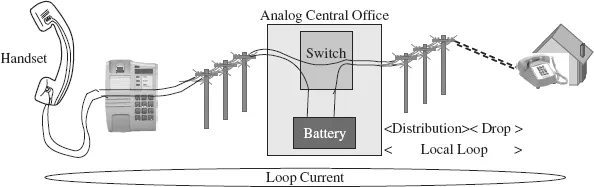
Figure 1.1 describes the original telephone technology, the analog phone or POTS line—Bell’s great invention. The phone at the house or office connects to the telco’s central office over a 2-wire copper line. The copper wires are twisted to reduce interference from external sources, such as AM radio stations and large electrical motors, but are not shielded by an external metal wrap—hence the term unshielded twisted pair (UTP). Electrical current to operate the phone comes from the battery in the central office; the phone needs no other power supply. Power from the CO was necessary when the first phones were installed because at that time lighting was by gas. Not many homes (and not all offices) had electricity.
Electrical current flows in a loop from end to end, through both phones. The portion of the connection between the customer and the CO came to be called the “local loop.” The transmitter in the mouth piece varies the rate of current flow in response to the sound waves from a talker’s mouth. Since the current flows in a loop, the same changes occur at the receiver where the miniature audio speaker in the earpiece reproduces the talker’s voice.
The system grew more complex as automatic switches took over from live operators, but the legacy signaling system is outside the scope of this work. For more information, see The Guide to T-1 Networking.
1.2 THE DIGITAL PSTN
The digital revolution hit the network in the 1960s with the deployment of channel banks. These multiplexers combine 24 analog circuits (2-wire POTS, 4-wire E&M, and other types) onto two twisted pairs, one for each direction, in the digital format that came to be known as T-1.
The reduction in wire count applied first on the trunk lines between central offices. The COs had room to house the new equipment, but more important, the cable ducts buried in the streets of major cities were filling up. The phone company couldn’t easily add more copper cables to fill the need for additional trunks between switches.
There was an added benefit to digital transmission: better sound quality. In most situations the 1’s and 0’s on the T-1 line survived intact, even if some analog noise were added by arcing motors, radio stations, or other sources. The receivers in the channel banks correctly recognized even a slightly distorted “1” as different from a “0,” so the output sound wasn’t impaired.
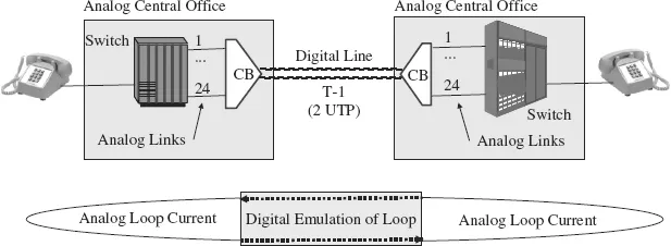
Digital transmission between analog switches looks like Figure 1.2. The transition from analog to digital for inter-office trunks was relatively easy and left other network devices in place. In this early form of digital telephony, the capacity of the T-1 line divides into 24 fixed channels based on time division multiplexing (TDM). That is, the 24 analog inputs take turns in strict rotation to send one byte of digitally encoded voice that represents a sample of the analog input loudness (the instantaneous volume level). The receiver converts that byte into a matching output level.
The Nyquist theorem regarding information transmission proved that if the samples were sent at a rate that was at least twice the highest audio frequency of the analog input, then the reproduction in the output at the receiver would be consistent with the input (reproducible results). Design compromises and precedents from analog telephones settled on a voice frequency range of 300 to 3300 Hz. Cutting off everything under 300 Hz eliminated AC hum and matched the limited capability of handset hardware to reproduce low frequencies. The top of 3300 Hz fit within what was then the standard for analog multiplexing: 4000 Hz for each analog channel.
To ensure that the sampling rate exceeded twice the highest voice frequency, the chosen sampling rate was 8000 per second. Each channel, then, generates 8 × 8000 = 64 kbit/s. This rate, the lowest in the digital multiplexing hierarchy, is numbered the way engineers start to count, with zero. Digital signal 0 (DS-0) is the fundamental building block of the TDM hierarchy in circuit-switched voice networks.
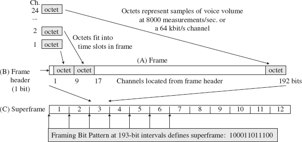
The T-1 bit rate is the sum of 24 channels plus an extra framing bit per cycle of 24 channels, a T-1 frame (Figure 1.3). This format continues in use as the way bits are organized on a primary rate interface (PRI) ISDN line. One of the DS-0s on a PRI, the D channel, carries only signaling messages, or what was called data because it wasn’t voice.
In any time division multiplexer, the basic frame consists of a string of bits marked in some way by a unique signature element which defines the frame (A). Some link protocols reserve a “start of frame character” that has no other use and never appears inside a frame.
In T-1 and PRI, the marker is a single F bit (B). One bit alone doesn’t allow a receiver to identify the start of the frame. The structure of a superframe (C) built up from 12 frames makes room for a fixed pattern across the superframe: 100011011100. The framing bit pattern allows the receiver to identify the locations of the F bits and from them the groups of bits associated with each channel. An extended superframe (ESF) of 24 frames uses a more complex pattern of F bits that includes a data channel.
The result is the now familiar T-1 bit rate:
Keep in mind that channel banks operate continuously. For each analog input (even if it is silent) the time slot on the DS-1 formatted line carries a byte of “sound” in every one of the 8000 frames per second. The capacity of the line is dedicated to the port on the channel bank, whether or not it is in use. In effect the digital transmission system of channel banks and T-1 lines (the original digital transmission technology) emulates the current flow in the analog local loop. T-1 transmission could also be compared to a moving sidewalk seen at most major airports. It runs at a constant rate whether or not there are passengers on it.
More precisely, the multiplexing format is DS-0; T-1 is a transmission technology on two twisted pairs that requires a repeater every mile but can be extended up to 50 miles. Digital subscriber line (DSL) equipment has largely displaced T-1 in local loop, with a longer reach at 1.5 Mbit/s without a repeater, but is more difficult to extend. Optical fiber now dominates between COs.
Some references to TDM-defined voice channels call it wasteful of bandwidth, but such a judgment should also take into account two other factors:
1. Low overhead: only 1/48 of a bit per octet sample is enough to identify the channels. Only half the F bits are used for ESF framing; the other 12 F bits are a data channel.
2. Low latency: each channel has a reserved spot in every frame. The latest byte from the speaker’s voice digitizer need wait no more than 1/8000 second (125 microseconds, μs) for the next frame to carry it away on the T-1 line.
Dedicated capacity per call prevents interference between users. One caller shouting can’t affect another who is whispering. With digital transmission, quality is consistently high. All callers who get connections receive the same high quality of service. Hold these thoughts for comparison to VoIP later.
Years after the first T-1 lines were installed between central offices, subscriber lines remained individual copper pairs from the switch in the CO to the telephone. Huge cables with thousands of pairs, laid from the CO to a large office building or to a residential neighborhood, had to be spliced by hand each time another reel of cable was added to the run. The biggest reel could hold as little as 1000 ft of a 4000-pair cable. Pieces of cable rarely exceed 1 mile, and the largest cables were installed mostly within large buildings.
The standard service area for a CO is measured by the length of its local loops: 12,000 feet is a common goal for the longest loops out of an office, which typically required splicing those cables once or twice.
When CO switches became digital, the channel bank was adapted to become an extension of the CO switch, with digital T-1 connections for most of the d...